4
ENGLISH
GENERAL
Read carefully the instructions before installing this
unit. Verify the technical characteristics of the motor in
order to assure the compatibility with the device.
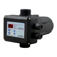
DESCRIPTION (diagram A)
This device is an electronic pump controller with in-
tegrated digital manometer an instantaneous lecture
of the motor load. It manages the start and stop of a
single-phase pump up to 2.2 kW (3 HP). It can operate
mode. The start pressure -and the stop pressure in
pressostatic mode- are easily adjustable through the
users control panel.
This device protects the pump against overload (only
DGplus and DGM2), minimal pressure and dry-running
operation.
CLASSIFICATION AND TYPE
According to IEC 60730-1 and EN 60730-1 this unit
is a control sensor device, electronic, independent
assembly, with action type 1B (microdisconnection).
Operating value: I <20% I learned. Pollution degree 2
-
OPERATING CHARACTERISTICS (diagram C)
• 2 modes of operation: pressure dependent mode
• Adjustable start and stop pressure.
• Integrated digital pressure gauge with bar and psi
indication.
• Inner pressure transmitter.
• Integrated non-return valve.
•
indication.
• Protection against minimum pressure.
• Overcurrent protection with automatic restore
attempts (only DGplus and DGM2).
• ART function (Automatic Reset Test). It can be
attempts.
• APR function (Anti-blocking Periodic Routine).
•
• Manual start push-button (ENTER).
• Control panel with 3-digit display, LED indicator
lights and push-buttons
• Volt-free contact for monitoring the alarms displa-
yed in the screen (only version A).
• Stand-by mode.
TECHNICAL CHARACTERISTICS
• Rated motor power 0,37-2,2KW
• Power supply ~1 x 110-230Vac
•
•
•
•
•
•
•
•
•
•
•
• Net weight (without cables) 1,3 kg
*Plugs and sockets built into the wiring of the
device could modify the declared IP rating.
HIDRAULIC INSTALLATION (diagram A)
Before proceeding with hydraulic connection
it is essential to prime the pump correctly. This
unit must be installed in a vertical position (arrows in
upward position), thus connecting the inlet opening
directly to the pump outlet; and the outlet to the
network. The following accessories are recommended:
-
and vibrations, ball valve which permits the isolation
of the pump from the net, a tap (A) at the same level
of the unit FIG 1).
In pressure dependent mode or in applications
with cut-in pressures higher than 3 bar is compul-
sory the installation of a pneumatic tank.
ELECTRIC CONNECTION (diagram B)
The electric connection must be performed by
-
lation of each country. Before doing manipulations
inside the device, it must be disconnected from the
electric supply.
Wrong connection could spoil the electronic circuit.
The manufacturer declines all responsability in
damages caused by wrong connections.
Check if power supply is beetween 110-230V.
If you have purchased the unit without cables follow
diagram B:
•
enough to the power installed:
• Do the pump connection U, V and .
• Do the power supply connection L, N and .
• The earth conductor must be longer than the
the assembly and the last one to be disconnected
during the dismantling. The earth conductors
connections are compulsory!
• Volt-free contact for monitoring the alarms displayed
in the screen (only versions DGPLUS/DGM-A).
• Maximum switching voltage: 250VAC / 220VDC.
• Maximum switching power: 62,5VA / 30W
CONTROL PANEL (diagram C)
• O means lit LED light.
•
DISPLAY ACTION
OPERATION
MODE
Is showed on screen instantaneous
pressure or instantaneous current con-
sumption (only DGplus and DGM2).
ADJUSTMENT
MODE
Is displayed on screen the adjusted
Is displayed the adjusted rated current.
ALARM MODE Is displayed the alarm code.
STAND-BY
MODE
BASIC
CONFIG.
Is displayed the sequence of basic con-
ADVANCED
CONFIG.
Is displayed the sequence of advanced
 Loading...