3
PBUTTON TOUCH ACTION
click!
From state ON: unit OFF.
From state OFF: the pump starts and keeps opera
ting until reaching Pstop.
From any confi guration MENU: the parameter
value is accepted.
HOLD
DOWN
From state ON: unit OFF.
From state OFF: the pump starts and keeps opera
ting until the pushbutton is released.
click! Pstart is displayed on the screen for 3 seconds.
3” Pstart adjustment mode.
click! Pstop is displayed on the screen for 3 seconds.
3” Pstop adjustment mode.
click!
Is displayed on the screen instantaneous current
consumption.
If it is already displayed then we switch to instanta
neous pressure view.
3” Rated current adjustment.
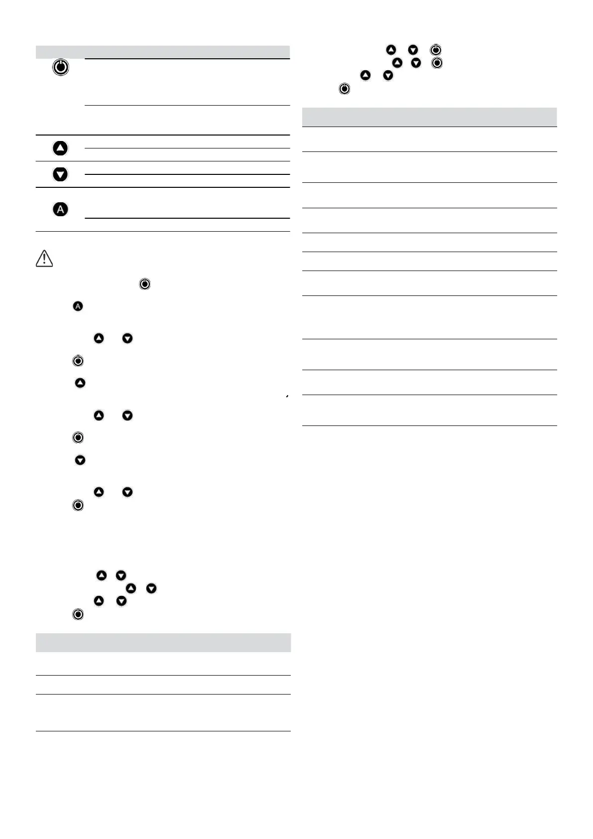
STARTUP diagram C
Before starting the device please read the previous sections, espe
cially “Hydraulic Installation” and “Electrical connection”.
Follow next steps:
1. Start the device by pressing .
2. Only for type SW2 set the pump rated current intensity value.
Press during 3 seconds.
The current intensity value is displayed on screen, LED A lights up and
display is fl ashing.
By mean of and is adjusted the rated current refl ected in the
characteristics plate of the motor. See Note 1.
Press for validation.
3. Set the cutin start pressure:
Press during 3 seconds.
The start pressure value is displayed on screen, LED START lights up
and display is fl ashing.
By mean of and is adjusted the start pressure from 0,5 to 7
bar.
Press for validation.
4. Set the cutout stop pressure:
Press during 3 seconds.
The stop pressure value is displayed on screen, LED STOP lights up
and display is fl ashing.
By mean of and is adjusted the stop pressure from 1 to 8 bar.
Press for validation.
5. The unit is ready to operate but more optional adjustments can be set
through basic and advanced MENUS. See the next chapter.
Remark 1: it is important to introduce exactly the rated current
specifi ed on the nameplate of the pump.
BASIC MENU + diagram C
Press simultaneously + during 5 seconds.
By mean of or the values can be changed.
Press for validation.
The parameters sequence is:
it TYPE SYSTEM REACTION
FACTORY
SETTING
1 BAR P
We can select the pressure units displayed
beetween bar and psi.
bar
2 rc0 rc1
Fastcycling alarm activated rc1 or disabled
rc0.
rc0
3 r.01 r.99
Only if fastcycling alarm has been activated in
the previous step rc1. It can be choosed the
maximum time period between 3 consecuti
ve starts that will be considered fast cycling
between 1 sec. and 99 sec.
5 se
conds
4 Sb0 Sb1
Standby mode activated Sb1, for low power
consumption, or disabled Sb0.
Sb0
ADVANCED MENU + +
Press simultaneously + + during 5 seconds.
By mean of or the values can be changed.
Press for validation.
The parameters sequence is:
it TYPE SYSTEM REACTION
FACTORY
SETTING
1 nc no
Select the operation MODE as a conventio
nal pressure switch nc = normally closed or
reverse no = normally open.
nc
2 E00 E01/02
Only Switchmatic2. Select the operation
mode Individual E00 or Master/Slave E01/
E02 in case of be assembled in groups of
two pumps.
E00
3 d.05 d.1
Only Switchmatic 2. Sets the minimum
diff erential between Pstart 1 and Pstart 2
and/or Pstop 1 and Pstop 2.
d.05
4 ct0 ct9
Sets a time delay between 0 and 9 seconds
to the start is not available in synchronized
operation mode.
ct0
5 dt0 dt9
Sets a time delay between 0 and 9 seconds
to the stop.
dt0
6 Ar0 Ar1
Activation of the automatic restore system
ART Ar1 o disable Ar0.
Ar0
7 d0.5 d1.5
Sets the minimum diff erential between
Pstart and Pstop values between 0.5 bar 7,0
psi and 1.5 bar 21.7 psi.
0,5 bar
7,0psi
8 P0.0 Px.x
It allows setting a minimum operating
pressure under which the device would
determine dryrunning operation. It is very
usefull in the basic model SWITCHMATIC
where there is no reading of current intensi
ty drawn. See Note 2.
0 bar
0 psi
9 t05 t99
Set the time period between 5 and 99
seconds below the minimum operating
pressure that will be considered a dry
running operation.
20”
10 c10 c30
It allows setting a % of nominal current
above which the device will activate the
overcurrent protection.
c20
11 dr0 dr1
Only for SWITCHMATIC 2. It allows the
activation of accurate dryrunning detection
DR1 or to disable it DR0. See chapter
ACCURATE DRYRUNNING DETECTION.
dr0
Remark 2:
Basic SWITCHMATIC can only detect dryrunning operation
through the minimum pressure. This means that plumber must
determine the water column of the installation, the start pressu
re of the pump and place the minimum pressure below the start
pressure.
It can also occur that pumping system is running out of its curve so
that the pump is unable to provide the minimum pressure because
the fl ow requirement is excessive. In this case SWITCHMATIC would
activate a false dryrunning alarm.
If these concepts are not clear, it is preferable not confi gure this
protection or install the SWITCHMATIC 2 with accurate and easy
setting of dryrun detection.

 Loading...