Installation
Read this section to learn how the vision system connects to standard components
and accessories. For a list of options and accessories, contact your Cognex sales
representative.
Note: Cables are sold separately.
CAUTION: All cable connectors are keyed to fit the connectors on the vision
system. Do not force the connections or damage may occur.
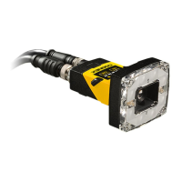
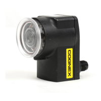
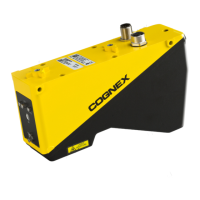
Mount the Vision System: Top Housing
1. Align the holes on the mounting surface with the mounting holes on the
vision system.
2. Insert the M4 screws into the top mounting holes and tighten. The maximum
torque is2.00Nm (17.70in-lb). Do not exceed the maximum insertion depth
of 8 mm for the M4 screws. The maximum insertion depth does not include
the thicknessof the mounting material.
3
 Loading...