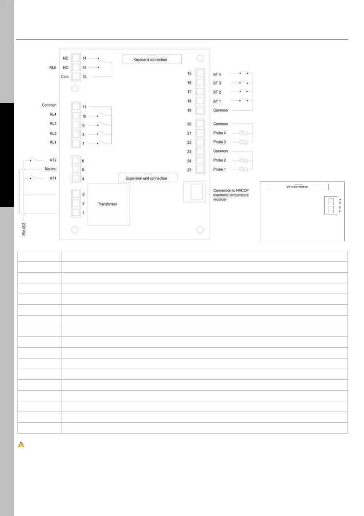
Compressor management output
Pump-down solenoid valve management output
Evaporator fan management output
Defrost management output
UV lamp management output (optional)
Low pressure alarm digital input (not used)
Compressor thermal cutout alarm digital input (not used)
Door microswitch digital input
High pressure alarm digital input
Evaporator sensor PTC input
Compartment sensor PTC input
Heated probe input (optional)
12V~40VA power supply (optional)
The expansion board is only fitted in the event the appliance features the heated needle probe.