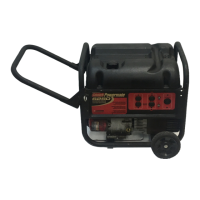
MAJOR GENERATOR FEATURES
10 HP Briggs & Stratton OHV engine
* Low oil sensor
Receptacles on control panel
* 6 gallon plastic fuel tank
* Portability Kit
CONTROLPANEL
A. 120 V, 20 Ampere Duplex Receptacle
This duplex {s setit so that 20 ames of current may De
drawn from each half of the receptacle However. tota power
drawn must be kept within nameplate ratings. These
receptacles may be used along w_ththe tw_stlock receotacIe
provided the generator Jsnot overloaded.
B. 120/240 V, 20 Am pere Twistlock Receptacle
A maximum of 20 amps may De drawn from the 120/240
volt receptacle, provided it _sthe onl_, receptacle used
However, current must be _imited to the nameplate raung If the
120/240 volt receptacle _sused along _tth the 120 volt
receptacle, the tots toaa arawn must not exceed the nameplate
ratings.
C. Circuit Breakers
The receptacles are 0rotected by an AC circuit breaker If
the generator is overloaded or an external short circuit occurs
the circuit breaker will trip If this occurs disconnect al
electrical _oaas aria try to determine the cause of the problem
before attempting to use the genera[or again. If overloading
causes the circuit breaker to the reduce the Ioac NOTE:
Continuous tripping of the circuit breaker may cause
damage to generator or equipment, The circuit breaker maj
be reset by pusnmg the button of the breaker.
fB
• Oa, : o 0
PORTABILITY KIT INSTALLATION
TOOLS REQUIRED: I/2" and 9/16" sockets and ratchets
bIock/s/of wood minimum of 6_'tail'
Refer to the parts list and drawing on pages 8 and 9.
WHEEL INSTALLATION
1. Block up end of generator opposite the fuel tank cap to
install whee_ k_1
2 Insert wheel spacer (item 43} into the center of the whee
(item 35).
3. Stide 3/8 x 3.5" bolt (item 41) through the whee (item 35)
then through the whee_ bracket on the carne! _4ththe
offset side of the wnee_ hub against the wheel bracket.
4. Thread 3/8 nyloc nut (item 42) onto the bolt and tlgn_en to
securely clamp the wheel assemb • to the tubing
5. Repeat above instructions for the remaining wnee
FOOT INSTALLATION
1. Blocking up the engine side of the generator, place a
spacer (item 38( aria a foot (item 37) under the carrier
channel. Thread a 5/16-18 x 3" bolt (item 36) through the
mounting holes and thread a 5/16 washer (item 40) aria a
5/16 nyloc nut (item 16) to the bolt to secure the foot to the
career. Caution: Do not over tighten sotbat the foot
material collapses.
2. Repeat step 1 for the remaining foot.
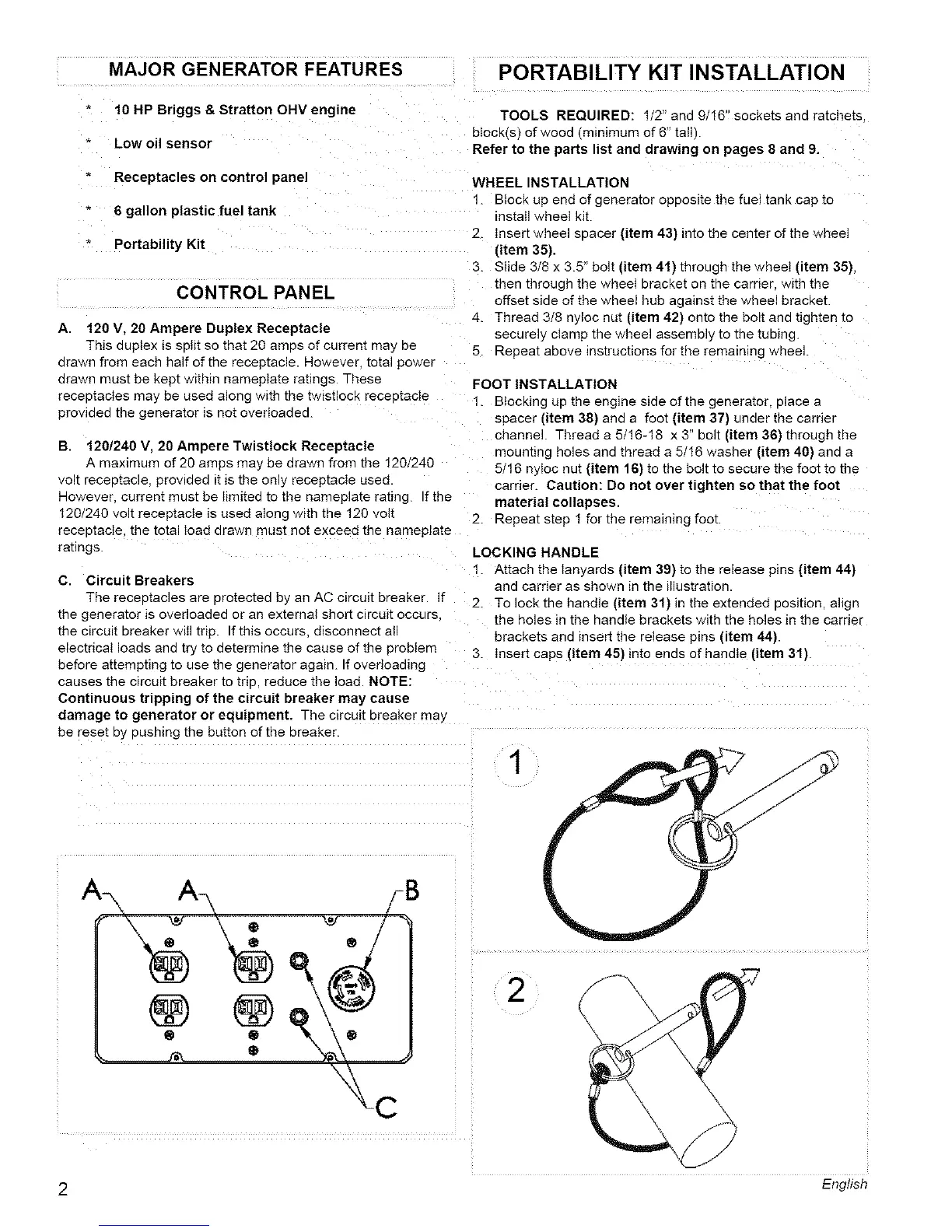
LOCKING HANDLE
1. Attach tile lanyaras (item 39) to the release eins (item 44)
and carrier as shown in the illustration
2. To Iockthe handle (item 3!) in the extended 3osMon angn
the holes In the ltandle brackets with the holes In the carrier
brackets ana insert the release pins (item 44).
3. Insert caps (item 45) into ends of handle (item 31).
1
\
2 English