ROTA 400 Collomix GmbH
D-85080 Gaimersheim
4 Version G 1.5-18
1. Layout Drawings
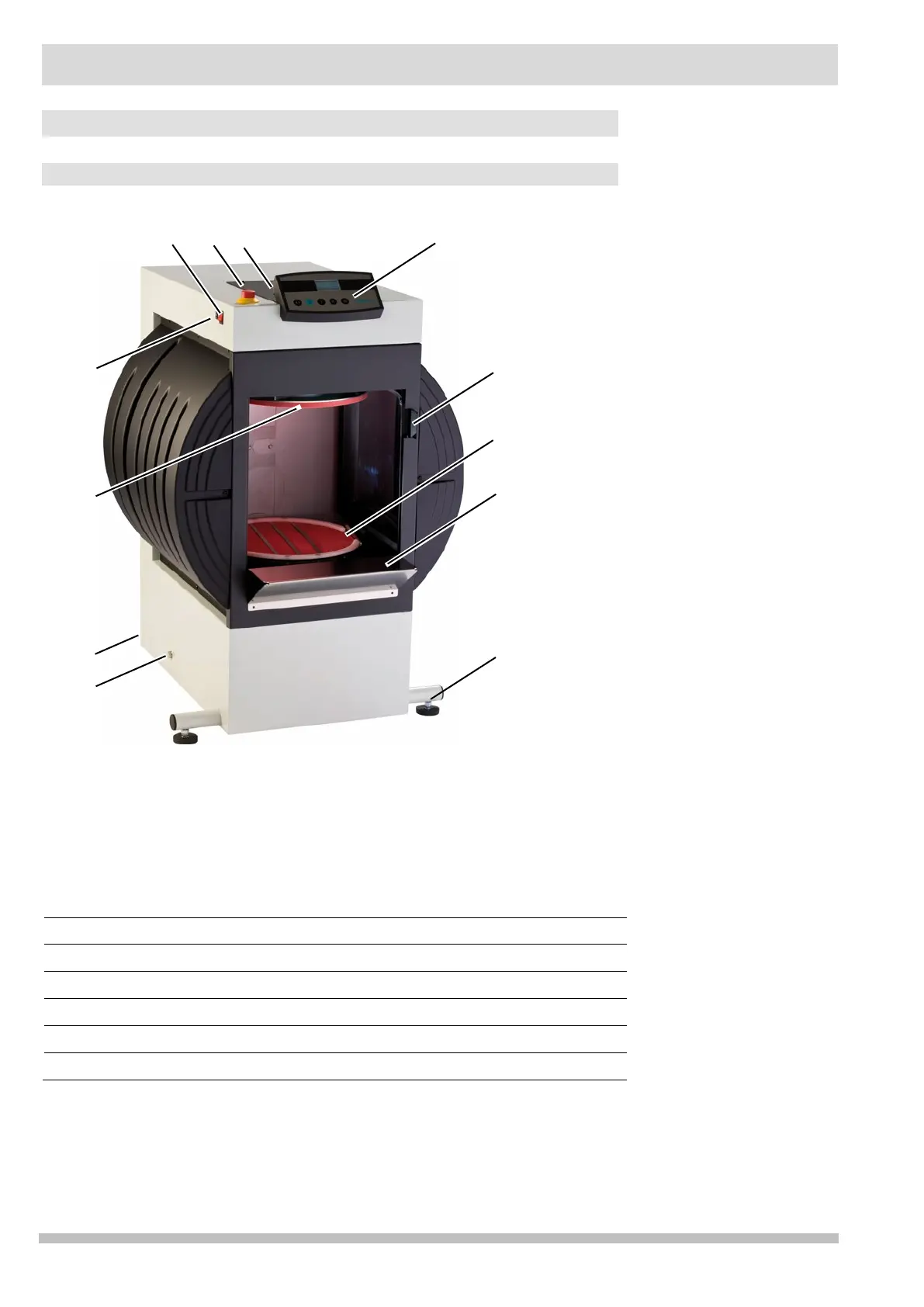
1.1 Machine components
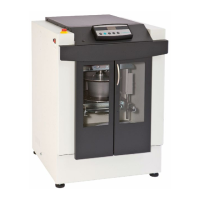
Machine components
1. Screw for transport roller 7. Manual door release
2. Line connector and main fuse 8. Control panel
3. Upper clamping plate 9. Door
4. Control system fuse 10. Lower clamping plate
5. Main switch 11. Loading shelf
6. Emergency Stop 12. Machine legs