3
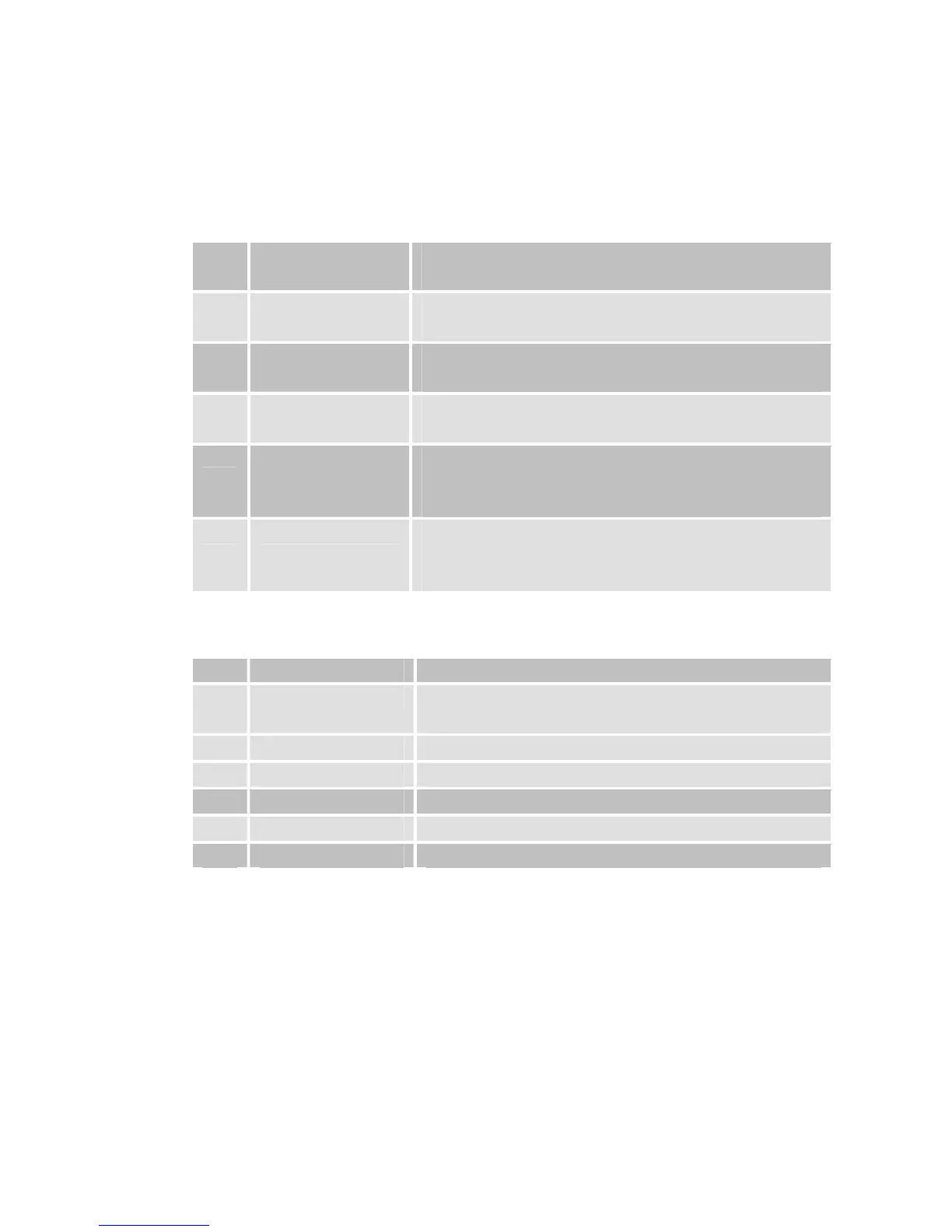
Overview of equipment
Front side of the receiver
1
- Infrared sensor for the signals of the
remote control
2
LED STBY LED is only illuminated if the receiver is in
standby mode
3
LED ON LED is illuminated if the receiver is
switched on
4
Standby Switches on and switches to the standby
mode
5
CH+ key Switches to the next higher channel
location
Cursor moves up
6
CH- key Switches to the next lower channel
location
Cursor moves down
Rear side of the receiver
1
LNB IN LNB connection for the antenna cable
2
IF OUT LNB connection for an analogue satellite
receiver in standby mode
3
TV (output) SCART connection for the TV set
4
DC IN 12V Connection 12V/power pack
5
AUDIO R Analogue audio connection R(Right)
6
AUDIO L Analogue audio connection L(Left)
7
Video RCA video connection