USER MANUAL FOR COMFLEX-6Q00 5W
ENU STATUS: 1-0-1 Copyright - refer to title page Page 30
SC/APC optical fiber access port
LED indicator. See Chapter 4 for the description of each indicator.
F connector for BTS alarm.
connects PC with equipment for local and remote
Reserved RJ45 port for remote monit
4 for the detailed description.
Expansion FOU communication connector
11. POI POI communication connector
12. AUX Expansion unit communication connector
13. MODEM Optional modem unit communication connector
14. 28V+ GND Expansion FOU and RFU external power supply
15. EXT_PSU Redundant PSU power supply connector
16. LI_BAT Optional Li-Battery unit power supply connector
17. /
18. UL1,DL1; UL2,DL2 Reserved for RF interface of extended FOU
19.
Grounding connector for rack
20. Power Supply Main PSU AC/DC output port
21. LI_BAT Power supply connector of optional Li-Battery unit
ANT
Communication connector / Antenna port of optional moedem unit
50Hz/60Hz
Redundant PSU AC/DC output port
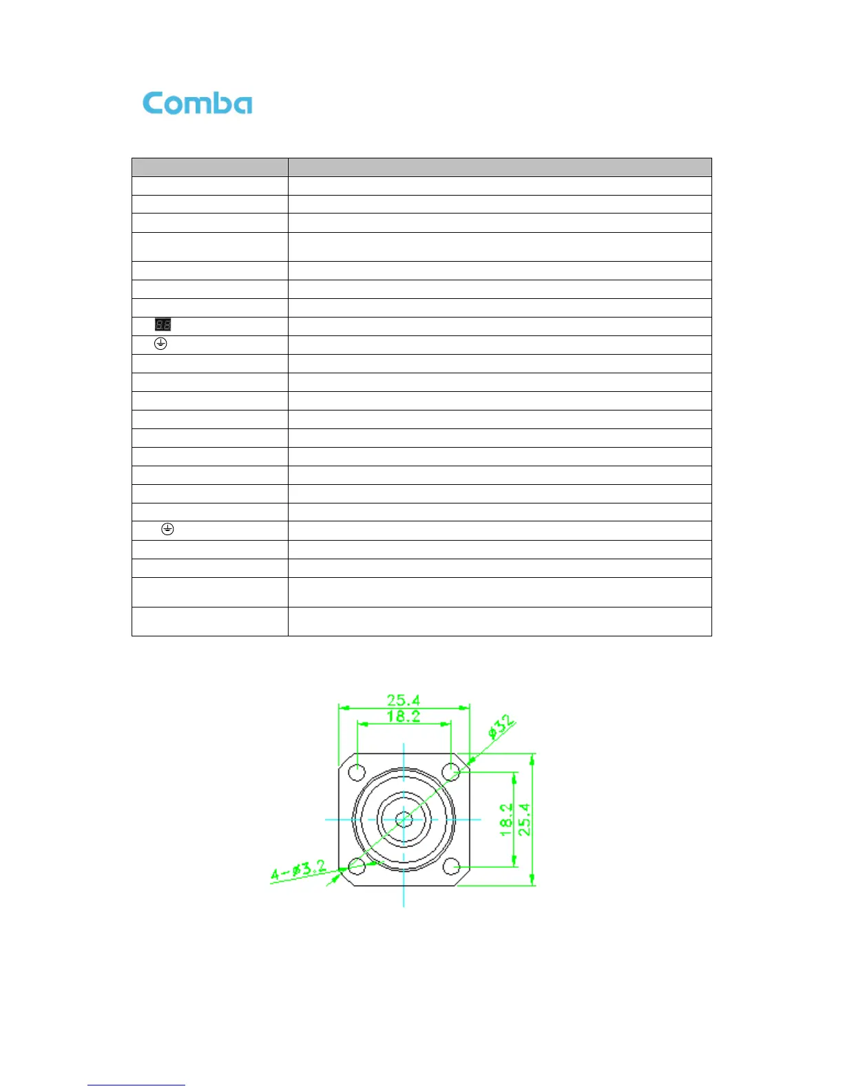
*4.3-10 Female Dimension is shown in figure below.
Figure 25: 4.3-10 Female Dimension