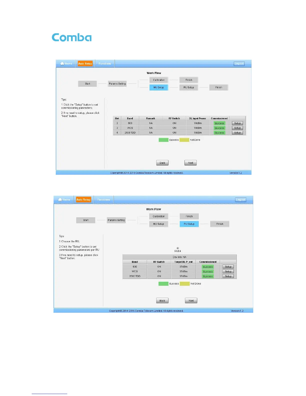
Step 8: After Calibration is finished, go to MU Setup as in Figure 72, then RU Setup shown in Figure 73
Figure 71: Commissioning Procedure – MU Setup
Note: RU Setup includes “Remark”, “RF Switch”, “DL Input Power”.
Figure 72: Commissioning Procedure – RU Setup
Note: RU Setup includes “RF Switch”, “Target DL P_out”
Step 9: Back to [Home] page, set all 2500 TDD channel Working Mode to “Normal”, and set the right TD-
LTE “DL/UL Slot Configuration” and “Special Subframe Configuration”, as in Figure 67.