FT GEN 23
IT
EN
FR
NL
DE
ES
PT
IT
EN
FT GEN 234
IT EN
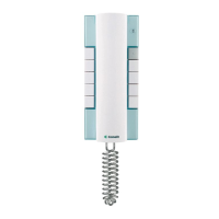
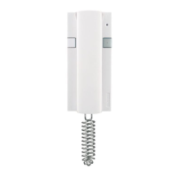
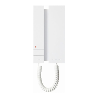
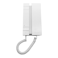
Citofono Art. 2602U.
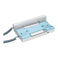
Fig. 8
1. Morsetti connessione impianto:
A apriporta
B microfono a condensatore
C comune
D chiamata (elettronica o meccanica)
E altoparlante
C2 P2 morsetti pulsante P2 C. NO. 24V 100mA dedicato a servizi vari
2. Selettore chiamata:
E = Suoneria elettronica
M = Chiamata con ronzatore
3. Regolazione volume microfono.
4. Regolazione volume altoparlante.
5. Regolazione volume microfono.
6. J1 jumper di configurazione.
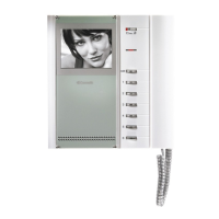
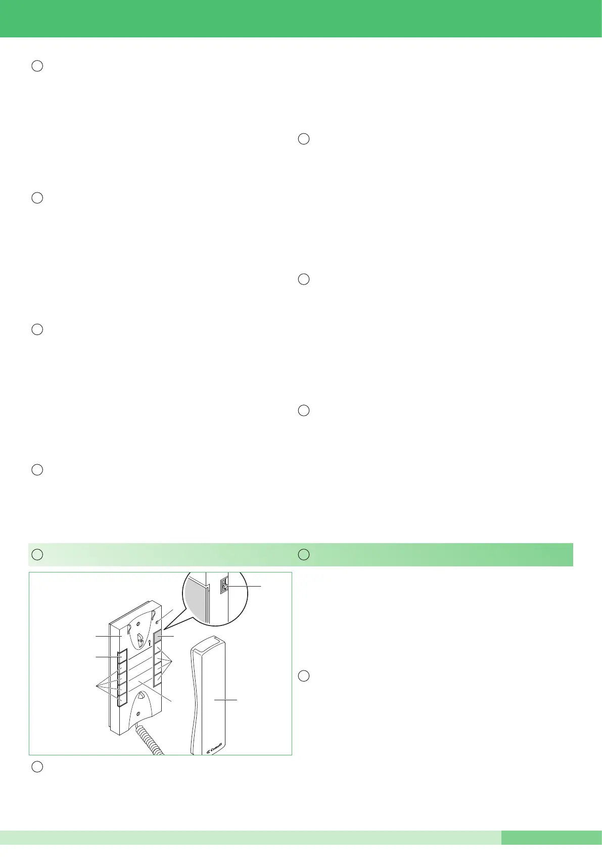
1. Selettore suoneria/servizio Privacy a 3 posizioni:
Posizione alto: Suoneria volume massimo.
Posizione centrale: Suoneria volume medio.
Posizione basso : Attivazione funzione Privacy
(per servizio Privacy si intende lʼesclusione della chiamata dal posto esterno;
lʼattivazionedella funzione Privacy è evidenziata dalla comparsa di un
indicatore rosso in alto a destra).
2. Indicatore funzione Privacy
3. Pulsante 1 disponibile di serie per servizi vari.
4. Pulsante Apriporta A .
5. Pulsanti C. NO. o Led (MAX 4) opzionali per funzioni supplementari (A)
6. Cover intercambiabile Fig. 7 pag. 3.
7. Etichetta memo-pulsanti su cui è possibile riportare la funzione dei pulsanti
del citofono (da applicare sotto la cover intercambiabile) Fig. 7 pag. 3.
8. Cornetta citofono (sollevare la cornetta per iniziare la comunicazione).
(A) Pulsante disponibile con scheda opzionale Art. 1626.
Led di visualizzazione disponibile con scheda opzionale Art. 1627.
Door-entry phone Art. 2602U.
1. 3-position selector for Call tone/Privacy service:
High position: Call tone at maximum volume.
Central position: Call tone at medium volume.
Low position : Activation of Privacy service.
(Privacy service means exclusion of the call from the external unit. Activation of
the Privacy function is shown by a red indicator appearing in the top right corner).
2. Privacy function indicator.
3. Pushbutton 1 available as standard for various usages.
4. Key button A .
5. Optional C. NO. buttons or Leds (MAX 4) for additional functions (A)
6. Replaceable cover Fig. 7 pag. 3.
7. Button memo label where the door-entry phone button functions can be
indicated (to be applied to the door-entry phone under the Cover as shown
in Fig. 7 at page 3.
8. Door-entry phone handset (lift the handset to start communication).
(A) Button available with optional Art. 1626.
Signaling Led available with optional Art. 1627.
Fig. 8
1. Terminals for system connection:
A Door opener
B Condenser microphone
C Common
D Call (electronic or mechanical)
E Loudspeaker
C2 P2 terminals for button P2 C. NO. 24V 100mA dedicated to various usages
2. Call selector:
E = Electronic bell
M = Call with buzzer
3. Microphone volume adjustment
4. Loudspeaker volume adjustment
5. Microphone volume adjustment
6. J1 configuration jumper
Fig. 8
1. Bornes pour le raccordement du système :
A = Ouvre-porte
B = Micro à condensateur
C = Commun
D = Appel (électronique ou mécanique)
E = Haut-parleur
C2 P2 Bornes pour le bouton P2 C. NO. 24V 100mA dédié à diverses
utilisations
2. Sélecteur dʼappel :
E = Sonnerie électronique
M = Appel avec ronfleur
3. Réglage volume micro
4. Réglage volume haut-parleur
5. Réglage volume micro
6. J1 cavalier de configuration
Afb. 8
1. Klemmen voor aansluiting van het systeem:
A = Deuropener
B = (condensator) Microfoon
C = Common
D = Bel (electronisch of mechanisch)
E = Luidspreker
C2 P2 klemmen voor drukknop P2 C. NO. 24V 100mA bestemd voor
verschillende doeleinden
2. Oproepselector:
E = Electronisch
M = Mexhanische buzzer
3. Microfoon volume instelling
4. Luidspreker volume instelling
5. Microfoon volume instelling
6. J1 jumper de configuratie
Abb. 8
1. Anschlussklemmen zur Systemverbindung für folgende Elemente:
A = Türöffner
B = Kondensatormikrofon
C = Allgemein
D = Anruf (elektronisch oder mechanisch)
E = Lautsprecher
C2 P2 Taste P2 C. NO. 24V 100mA , kann für unterschiedliche Funktionen
programmiert werden
2. Rufwahlschalter:
E = Elektronische Klingel
M = Anruf mit Summer
3. Einstellung Mikrofon-Lautstärke
4. Einstellung Lautsprecher-Lautstärke
5. Einstellung Mikrofon-Lautstärke
6. J1 Konfigurationsjumper
Fig. 8
1. Terminales para la conexión del sistema:
A = Abrepuerta
B = Micrófono de condensador
C = Común
D = Llamada (electrónica o mecánica)
E = Altavoz
C2 P2 terminales para el pulsador P2 C. NO. 24V 100mA dedicado a varios usos
2. Selector de llamada:
E = Dispositivo sonoro electrónico
M = Llamada con zumbador
3. Regulación del volumen micrófono
4. Regulación del volumen altavoz
5. Regulación del volumen micrófono
6. J1 puente de configuración
Fig. 8
1. Terminais para ligação do sistema:
A = Trinco
B = Microfone com condensador
C = Comum
D = Chamada (eletrônica ou mecânica)
E = Alto-falante
C2 P2 terminais Botão P2 C. NO. 24V 100mA para usos vários
2. Seletor chamada:
E = Campainha eletrônica
M = Chamada com sinal sonoro
3. Regulação volume microfone
4. Regulação volume alto-falante
5. Regulação volume microfone
6. J1 jumper de configuração
 Loading...