EasyManua.ls Logo

Comelit Simplebus Color 2638 User Manual

Comelit Simplebus Color 2638
44 pages
To Next Page IconTo Next Page
Page #1 background imageLoading...
Page #1 background image
Assistenza tecnica Italia 0346/750090
Commerciale Italia 0346/750091
Technical service abroad (+39)0346750092
Export department (+39) 0346750093
PT
FICHA
TÉCNICA
IT
FOGLIO
TECNICO
EN
TECHNICAL
SHEET
FR
FEUILLE
TECHNIQUE
NL
TECHNISCHE
HANDLEIDING
DE
TECHNISCHES
DATENBLATT
ES
HOJA
TÉCNICA
FT SBC 04
Comelit Group S.p.A. - Via Don Arrigoni 5 - 24020 Rovetta S. Lorenzo BG Italy - tel. (+39) 0346 750 011 - fax (+39) 0346 71436
www.comelit.eu www.simplehome.eu info@comelit.it commerciale.italia@comelit.it export.department@comelit.it
Videocitofonia a colori con cablaggio a 2 fili
Colour door entry monitor with 2-wire cabling
Parlophonie et visiophonie avec câblage à 2 fils
Tweedraads video-intercomsysteem in kleur
Farbvideo-Türsprechanlage mit 2 -Draht-Leitung
Instalación de vídeo portero en color con 2 cables
Vídeo-intercomunicador a cores com cablagem de 2 fios

Table of Contents

Question and Answer IconNeed help?

Do you have a question about the Comelit Simplebus Color 2638 and is the answer not in the manual?

Comelit Simplebus Color 2638 Specifications

General IconGeneral
BrandComelit
ModelSimplebus Color 2638
CategoryIntercom System
LanguageEnglish

Summary

General Safety and Warnings

Core Components and Their Installation

Mixer-Power Supply Unit Art. 4888C Installation and Terminals

Installation guide and terminal details for the mixer-power supply unit.

Internal Units Installation Procedures

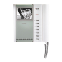
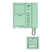
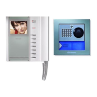
Steps for installing Planux monitors, Bravo/Genius monitors, and door-entry phones.

Bracket Art. 6114C/5714C/5814C Configuration

Configuration and terminal details for various monitor brackets.

Device Configuration and Programming

Device Identification and DIP Switch Programming

Process for identifying devices and programming them using DIP switches.

Programming Switching Devices and Buttons

Guide for programming the switching device Art. 1224A and unit buttons.

Dip Switch Programming Table

A reference table detailing DIP switch settings for various codes.

Installation Rules, Cable Specs, and System Operation

General Installation Rules and Guidelines

Key rules for installation, cable routing, and conductor characteristics.

System Operation and Monitor Functions

Explanation of system operation, calls, and specific monitor functions.

Wiring Diagrams and System Configurations

Powercom System Wiring Diagrams

Diagrams illustrating various Powercom system setups (1-door, 2-door, etc.).

Cascade and Branch Connection Diagrams

Diagrams showing cascade and branch connections for internal units and monitors.

System Variants and Specific Connections

Diagrams for LED usage, button functions, and connection variants.

Related product manuals