Do you have a question about the Comelit Simplebus Color 4888C and is the answer not in the manual?
Details on connecting power, external unit, and other devices.
How to set jumpers based on connected users.
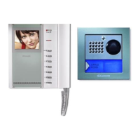
Illustrated steps for installing the Planux monitor with flush-mounted box.
Illustrated steps for installing the Planux monitor with surface-mounted box.
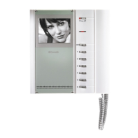
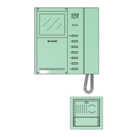
Illustrated steps for installing Bravo and Genius monitors.
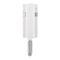
Illustrated steps for installing the Art. 2638 door-entry phone.
Controls for conversation, door lock, and menu navigation.
Keys for confirming selections and scrolling through options.
Buttons for custom functions like switchboard call or actuators.
Button for privacy or doctor call functions.
Terminals for connecting monitors and optional cards.
Terminals for system wiring and bus lines.
Jumpers and switches for configuration and settings.
Controls for ringtone, privacy, and system status indication.
Buttons for door lock, switchboard call, and self-ignition.
Buttons for generic actuators or doctor calls.
Screen for image display and controls for brightness/color.
Label for button functions and the monitor handset.
Controls for conversation, door lock, and menu navigation.
Keys for confirming selections and scrolling through options.
Buttons for custom functions like switchboard call or actuators.
Button for privacy or doctor call functions.
Connectors for monitor and system wiring.
Jumpers and switches for configuring bracket functions and button modes.
Button for opening doors and selector for ringtone/privacy.
Indicator for privacy function and terminals for system connection.
Jumpers and DIP switches for call functions and user codes.
Control for adjusting microphone volume.
General guidelines on using DIP switches for device identification.
Important notes regarding system occupancy and short circuits.
Step-by-step guide for programming the audio/video unit and modules.
How DIP switches define code ranges for the switching device.
Ensure distinct switching devices manage non-overlapping code intervals.
Comprehensive table mapping DIP switch settings to device codes.
Guidelines on wiring proximity, terminal usage, and cable management.
Rules for system capacity, line concentrators, and cascading devices.
Tables for assessing distances based on conductors and cable types.
Charts showing maximum distances for different cable types and categories.
Notes on using multi-pair or multi-core cables and voltage drop.
Diagrams illustrating system connections and distances.
Table detailing settings for Art. 1216 based on cable types.
How calls are received and communication is started.
Function of electric lock and visitor illumination.
How to use self-ignition and adjust monitor settings.
How monitors handle calls and operate in main/secondary modes.
How to enable/disable auto-ignition for Bravo/Genius monitors.
How to request video from external units for Bravo/Genius monitors.
How to start the ringtone selection process.
How to cycle through and select different ringtone types.
How to browse, select, and confirm the desired ringtone.
Illustrates the wiring for a 1-door Powercom video system.
Explains the function of the local door-opener button.
Illustrates the wiring for a 2-door Powercom video system.
Explains the function of the local door-opener button.
Diagram for a 1-door system with multiple mixer-power supplies.
Diagram for a 1-door system with main and secondary inputs.
Illustrates the wiring for a system with a remote camera module.
Indicates components requiring separate power supply.
References for programming and operating Art. 1259C.
Diagrams showing wiring for 1 main and 9 secondary video inputs.
Instruction to cut output resistance for specific outputs.
Explains limits on internal units and requirements for specific door-entry phones.
Diagrams illustrating cascade connection setups.
Instructions for connecting more than 9 branches using multiple concentrators.
Diagrams illustrating cascade connection of Art. 4834/9.
Explains limits for internal units and repetition devices, plus cable requirements.
Requirement for connecting a capacitor with inductive loads.
Diagram for cascading main monitors.
Diagram for cascading a third main monitor with local power.
Diagram for cascading 2 main and 1 secondary monitor.
Diagram for branching 2 main and 1 secondary monitor.
Diagram for cascading a third main monitor with local power.
Diagrams for cascading or branching secondary monitors.
Explains the function of LEDs on the bracket.
How to set button 1 for a generic actuator function.
How to use button P1 for different purposes on monitors.
How to use button P1 on Art. 2638 for different functions.
Diagram illustrating floor door call connection.
Diagram for a system variant with remote camera.
Diagram for digital video port connection with Art. 3340-3342.
Diagram for timed local door-opener connection.
| Brand | Comelit |
|---|---|
| Model | Simplebus Color 4888C |
| Category | Intercom System |
| Language | English |