Do you have a question about the Comelit 2708W and is the answer not in the manual?
Defines the product's intended application in audio and video communication systems.
Stresses qualified installation and proper wiring practices to prevent hazards.
Emphasizes adherence to manuals and system integrity for safe product usage.
Outlines routine cleaning and exclusive authorized repair procedures for Comelit products.
Limits Comelit's responsibility for non-intended use or failure to follow manual instructions.
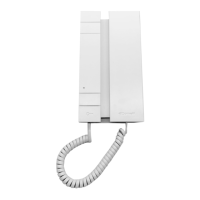
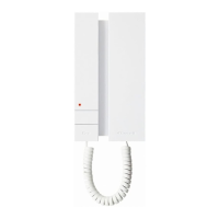
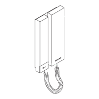
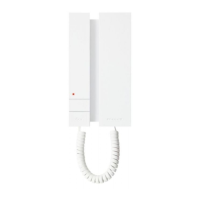
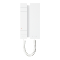
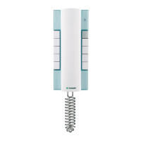
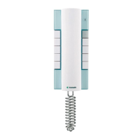
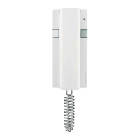
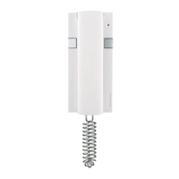
Details the physical parts of the 2708W unit, including loudspeaker, buttons, and indicators.
Explains terminal blocks, dip switches, and jumpers for configuration and connection.
Covers system type, audio/video support, mounting options, color, and button count.
Enumerates key functions like privacy, intercom calls, and actuator control.
Details user-adjustable settings such as loudspeaker and ringtone volume.
Provides specifications on voltage, power consumption, dimensions, weight, and environmental ratings.
Illustrates the step-by-step process for physically installing the device onto a surface.
Details how to connect the unit to the door entry riser and floor call button.
Explains how to set the unique user code using the dip switch on the phone card.
A comprehensive table mapping user codes to specific dip switch settings.
Demonstrates the dip switch configuration required for user code 200.
Specifies maximum cable lengths based on wire cross-section for optimal performance.
Outlines the maximum number of internal units and concurrent user codes supported.
Illustrates the complete wiring layout for the door-entry phone system.
| Type | Video Intercom |
|---|---|
| Resolution | 800 x 480 pixels |
| Connectivity | Wired |
| Handsfree | Yes |
| Colour | White |
| Mounting | Wall-mounted |