1414
EN
3
4
5
6
7B
7A
1
2
140-145 cm
115-125 cm
1 2 3A
3B 3C 4
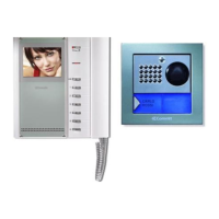
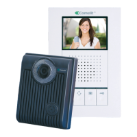
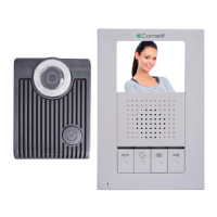
Art. 2608
Cannot be used for the intercom function.
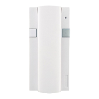
The door-entry phone should always be mounted using Art. 1214/2C as
illustrated in connection diagram GK/AACI on page 67.
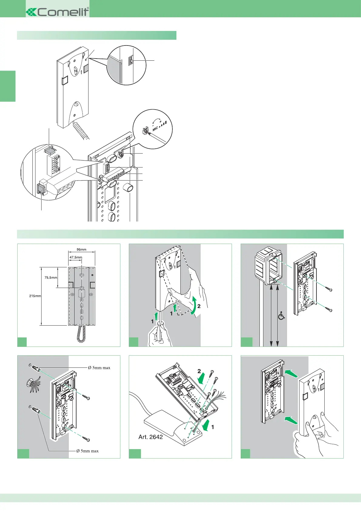
1 Privacy function indicator.
2 3-position ringtone/Privacy service selector:
High position: Maximum ringtone volume.
Middle position: Medium ringtone volume.
æ ,OWæPOSITIONæ0RIVACYæFUNCTIONæACTIVATION
Privacy service means exclusion of the call ringtone from the external
unit and switchboard; activation of the Privacy function is signalled by
a red indicator appearing at the top right-hand side).
3 Trimmer for adjusting the microphone volume.
4 User code programming microswitches.
5 System connection terminals:
L L Bus line connection.
CFP CFP Floor door call input.
P1 C1 Button P1 terminals for various purposes (contact C. NO 24 V -
100 mA max.) (remove CV1 and CV2, see variant SB/X3 on page 69).
S+ S- Terminals for call repetition device.
6 CV1 CV2 Jumpers to be removed in order to have potential-free C.
NO contact on button P1.
7A/7B JP1 Jumpers for selecting the switchboard call (position C) /
generic actuator (position A) function of button P1.
Description of buttons:
A Key button.
P1 Button P1 for switchboard call / generic actuator / button for various
purposes present on terminal block (P1 C1).
Clean using a damp cloth. Do not use alcohol or other aggressive
products.
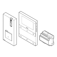
Installing door-entry phone Art. 2608
 Loading...