2727
EN
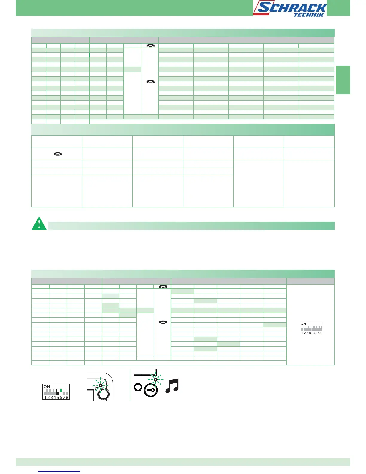
DIP S2 with Art. 6333
DIP 1 DIP 2 DIP 3 DIP 4 P1 P2
A
P3 P4 P5 P6 P7
0000
CCS AI
A
ACT D PAN K CCP
1000
ACT AI INT INTb D CCS PAN
0100
INT AI INTb ACT CCS CCP D
1100
ACT CCS CCP PAN K D AI
0010
ACT ACT ACT ACT ACT ACT ACT ACT
1010
INT ACT
A
CCS CCP INTb PAN K
0110
AI D K CCS CCP INTb INT
1110
INTb INT AI INT PAN D ACT
0001
CCS PAN D AI INT INTb CCP
1001
K CCS PAN CCP AI INT INTb
0101
CCP K PAN ACT INT AI CCS
1101
PAN CCP CCS K ACT D AI
0011
D INTb INT ACT AI CCS CCP
1011
INT INT INT INT INT INT INT
0111
NULL NULL NULL NULL NULL NULL NULL NULL NULL
1111
PROG
Legend
A
Lock- release CCS Switchboard call INTb
Two-family intercom
- for KIT only
Speech K
Guardian door-entry
phone call
NULL No function
ACT Actuator D Doctor
PROG
Programmed functions,
see pages 27-32
In this Dip switch setting,
the buttons control the
programmed functions; the
NON-programmed buttons
control functions referred to
on line 0000
AI Self-ignition PAN Panic
CCP Main switchboard call INT
Programmable
intercom, general or
selective
- general internal call
as standard for KIT and
Simplebus Top
DIP S2 with Art. 6333
DIP S1
DIP 1 DIP 2 DIP 3 DIP 4 P1 P2
A
P3 P4 P5 P6 P7
ADDRESS
0000
A
ACT
1000
ACT
0100
ACT
1100
ACT
0010
ACT ACT ACT ACT ACT ACT ACT ACT
1010
ACT
A
0110
1110
ACT
0001
1001
0101
ACT
1101
ACT
0011
ACT
1011
0111
1111
PROG
⇒
LED1
2
LED 2
Default button settings
)FæTHEæDEFAULTæSETTINGSæSEEæTABLEæONæPAGEææDOæNOTæREmECTæREQUIREMENTSæ
THEæBUTTONSæCANæBEæPROGRAMMEDæDIFFERENTLYæBYæCARRYINGæOUTæTHEæSTEPSæBELOW
At the end, set S2 DIP switches 1-2-3-4 to the combination 1111
(PROG setting in the configuration tables on pages 27, 28, 29). In this
dip switch setting, the buttons control the programmed functions;
General button programming warnings
the NON-programmed buttons control functions referred to on line
0000 (see table on page 27). Restore the user code setting on S1, see
table A on page 26.
%XAMPLE
ONæAæMONITORæWITHæUSERæCODEææ0æPROGRAMMINGææGENERICæACTUATORæ0ææ
CODEDæACTUATORæCODEæ
æ3ETæ3æ$)0æSWITCHææTOæTHEæCOMBINATIONæ
» LED 1 (red) flashes
æ2EFERæTOæTHEæTABLEæONæPAGEææANDæSELECTæAæCOMBINATIONæINæWHICHæTHEæ
ACTUATORæFUNCTIONæ!#4æISæLISTEDæFORæTHEæBUTTONSæYOUæWISHæTOæPROGRAM
%Gæ FORæ 0æ GENERICæ ACTUATORæ SETæ 3æ $)0æ SWITCHESæ æ TOæ THEæ
Programming buttons for generic or coded actuator
COMBINATIONææORææORææ0!#4æSETæ3æ$)0æSWITCHESæTOæTHEæ
COMBINATIONææGOæTOæPOINTæ
%Gæ FORæ 0æ CODEDæ ACTUATORæ CODEæ æ SETæ 3æ $)0æ SWITCHESæ æ
TOæTHEæCOMBINATIONææORææ0!#4æSETæ3æWITHæADDRESSææINæ
ACCORDANCEæWITHætable AæONæPAGEææGOæTOæPOINTæ
æ0RESSæANDæRELEASEæTHEæBUTTONæTOæBEæASSOCIATEDæWITHæTHEæFUNCTION
»LED 2 (blue) flashes 4 times
»confirmation tone
æ4OæEXITæPROGRAMMINGæMODEæSETæ3æ$)0æSWITCHESææTOæTHEæCOMBINATIONæ
00
» LED 1 (red) switches off
5. When programming is complete, set S2 DIP switches 1-2-3-4 to the
combination 1111. Restore the user code setting on S1, see table A
on page 26.
 Loading...