Do you have a question about the Comelit MT KIT 04 and is the answer not in the manual?
Overview of system capabilities, kits, and accessory compatibility.
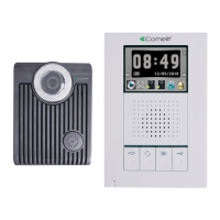
Technical specs, dimensions, and features of external units.
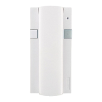
Specs and terminal block for the Art. 1205/B power supply.
Steps for mounting, wiring, and adjusting external units.
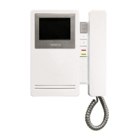
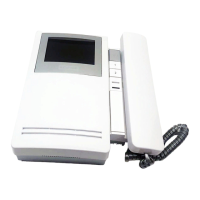
Monitor overview, components, functions, and technical specifications.
Specs and terminals of the bracket for monitor installation.
Desk mounting, removal, and label positioning procedures.
Guide for installing optional cards Art. 5733 and 5734.
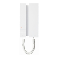
Installation, functions, and settings for Art. 2608, 2628, and 2610 telephones.
Table of cable specs and maximum allowed distances for system connections.
Tables for Art. 1216 settings, DIP switches, modes, and user code programming.
Explanation of microswitch addresses, monitor management, and pushbutton functions.
Details on intercom calls, Doctor function, and ringtone selection.
Settings for Art. 2610 telephone and Self Ignition/Video Request.
Procedure and table for programming special functions using Art. 4660/BK.
Information on expanding the system and programming Art. 4660/BK.
Basic wiring diagram for single-family kits Art. 8171.
Wiring diagram for two-family kits Art. 8173 with branched connection.
Wiring diagram for two-family kits Art. 8173 with cascade connection.
Diagram for two-family kits Art. 8173 expanded with second unit, branched.
Diagram for two-family kits Art. 8173 expanded with second unit, cascade.
Diagram for expanded two-family kit with secondary monitor and telephone, branched.
Diagram for expanded two-family kit with main monitor and telephone, cascade.
Diagram for single-family kit with additional power feeder Art. 1395.
Wiring diagram for using the remote camera module Art. 1259/A.
Diagram for connecting the video amplifier Art. 4833/A.
Diagram for adding a main monitor in parallel, cascade connection.
Diagram for adding a main monitor in parallel with branched connection.
Diagram for cascading main and secondary monitors with the same user code.
Diagram for adding a telephone in parallel, branched from the riser.
Diagram for connecting additional telephones, branched from the monitor.
Diagram for connecting additional telephones in cascade from the monitor.
Diagram for adding external light control using Art. 1256.
Diagram for adding an actuator Art. 1256.
Diagram for a timed local door lock release connection variant.
Diagram for connecting call repetition devices Art. 1229 or Art. 1122/A.
Diagram showing the use of Art. 1232 for filtering interference on S+ and S- terminals.
Diagram for adding a floor door call pushbutton.
Diagram illustrating the use of pushbutton 1 for various purposes.
Diagram showing the use of the LED 1 terminal for signalling.
Diagram for connecting 3 BRAVO KITS to a main entrance panel using Art. 4834/9.
Diagram for connecting up to 30 BRAVO KITS with a porter switchboard Art. 1998A.
| Brand | Comelit |
|---|---|
| Model | MT KIT 04 |
| Category | Intercom System |
| Language | English |