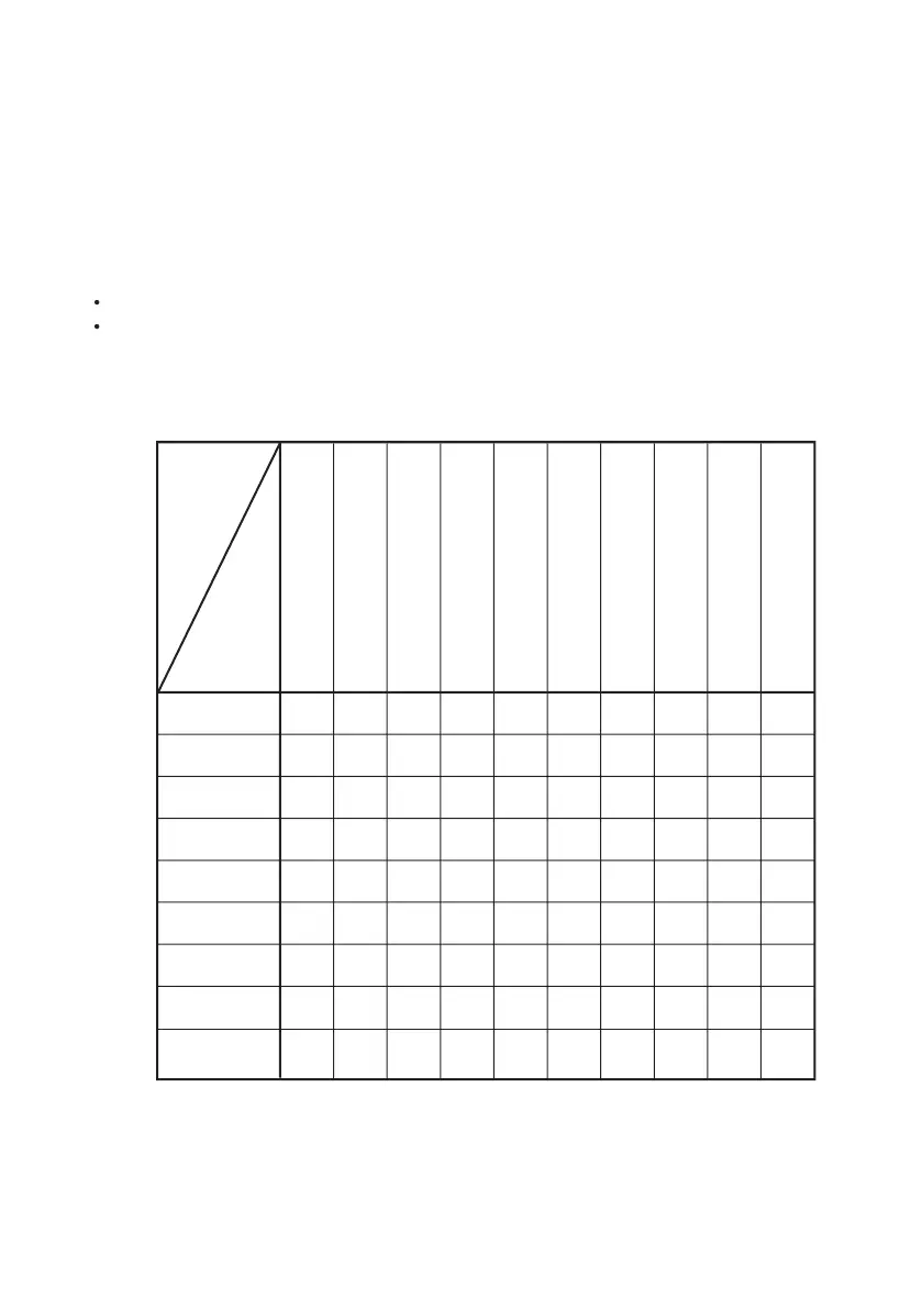
The many available applications for the pumps described in this manual are summarised in the
Always contact the dealer or the Manufacturer to identify the correct application. The applications
for the pump must always be executed according to the general rules of good mechanics. The
Manufacturer’s Service Centre is at the disposal of the installer for any further information.
2.2 HYDRAULIC CONNECTIONS
Follow the instructions for connections which are contained in section 5.2 of part one.
It is particularly important that the size of the intake circuit must be adequate so that the intake
coupling of the pump is not subject to:
pressure in excess of 0.1 bar / 1.45 psi:
vacuum in excess of 0.25 bar 7 3.63 psi.
Intake vacuum is tolerated up to a maximum of 0.45 bar/6.53 psi but only for periods of operation
of 10-15 minutes (normally enough time to ll up the tank of the machine where the pump is
STD = Standard
VA = Version available
(1) = Available with appropriate kit
(2) = Pulley available: 1 channel Z Øp 220
(3) = Reducer available: 1:6.44
(4) = Contact the dealer or Manufacturer for information on the correct kit to be used
Non-through shaft 1” 3/8
male Cardan
Overdrive
Through shaft 1” 3/8M Cardan
1” 3/8M Cardan
Non-through shaft cylindrical
30mm Ø
Through shaft 1” 3/8M Cardan
cylindrical 30mm Ø
Quick Coupling 1” 3/8F Cardan
Pulley
Hydraulic motor SAE flange
with two holes
Hydraulic pump group 2
Reducer