Probable Cause
Problem
Unit will not operate
All power inputs are not
connected to 12V+
Remote start in Service
mode LED is ON solid
Turn ignition key to ON
position, press and hold
service switch for 5 sec. LED
will go out
Crank time must be
increased.
Engine Cranks but not
long enough to allow
vehicle to start.
Ignition #1 (Yellow Wire)
is on wrong connector-
Ignition/Accessory #2
RS will not go into
Code Learning or
Programmning Mode.
Connect the main ignition
Input/Output to the Ignition
#1 connector on the Board.
To Exit mode: 1. Press brake
pedal, then Turn Ignition key
on, Press and hold Button
#2 for 5 seconds (lights will
flash 10 x's)
Check Brake switch input
(Yellow Wire) for (+) or
Hood input (Blue Wire)
for (-) shorted to ground
Connect red wire on access-
ory plug (red plug) to Factory
Alarm disarm wire.
Vehicle has a factory
alarm system.
Car Horn Honks and
Vehicle will not start.
RS in Automatic Cold
Start Activation Mode.
Vehicle starts without
pressing Remote
Transmitter.
Extend the green wire from
the main harness to a spark
plug wire (wrap around), put
dip switch #1 in the off
position.
Voltage sense is not
working. Use the spark
sense.
Vehicle cranks and
begins to run, then
shuts off.
Vehicle has theft deterrent
system that prevents
starting w/o key in ignition.
See manual on Passlock PATS
theft deterrent systems.
Vehicle cranks and
begins to run, then
shuts off.
Keyless Entry
operates but engine
will not start
Vehicle wil lnot
remotr start
Safety inputs are triggerd
SYSTEM CONTENTS
1
TROUBLE SHOOTING
10
Main inputs heavy gauge red
wires and red fused wire on
main harness must be
connected to 12V+
Place dip switch #3 to the
ON position
Suggestions
Each system contains the following components:
1- Brain Module
2- 4 Button Transmitters
1- External Receiver W/ harness
1- 6 Tone Siren
1- Shock Sensor Dual Zone W/ harness
1- 10 pin wiring harness
6- (12 G.) Wires W/2 Fuse Holders
1- 3 pin door lock harness
1- 3 pin wiring harness
1- 2 pin wiring harness
1- Red Status L.E.D.
1- Push Button Switch
Note: Read this instruction manual thoroughly.
Important: This unit is designed for a professional installation only.
Any installation performed by an unqualified installer,
will void the warranty.
AUTOMATIC TRANSMISSION ONLY
DO NOT INSTALL ON MANUAL TRANSMISSION
"" Manufacturer will not be responsible if any damage occurs on cars
with manual transmission ""
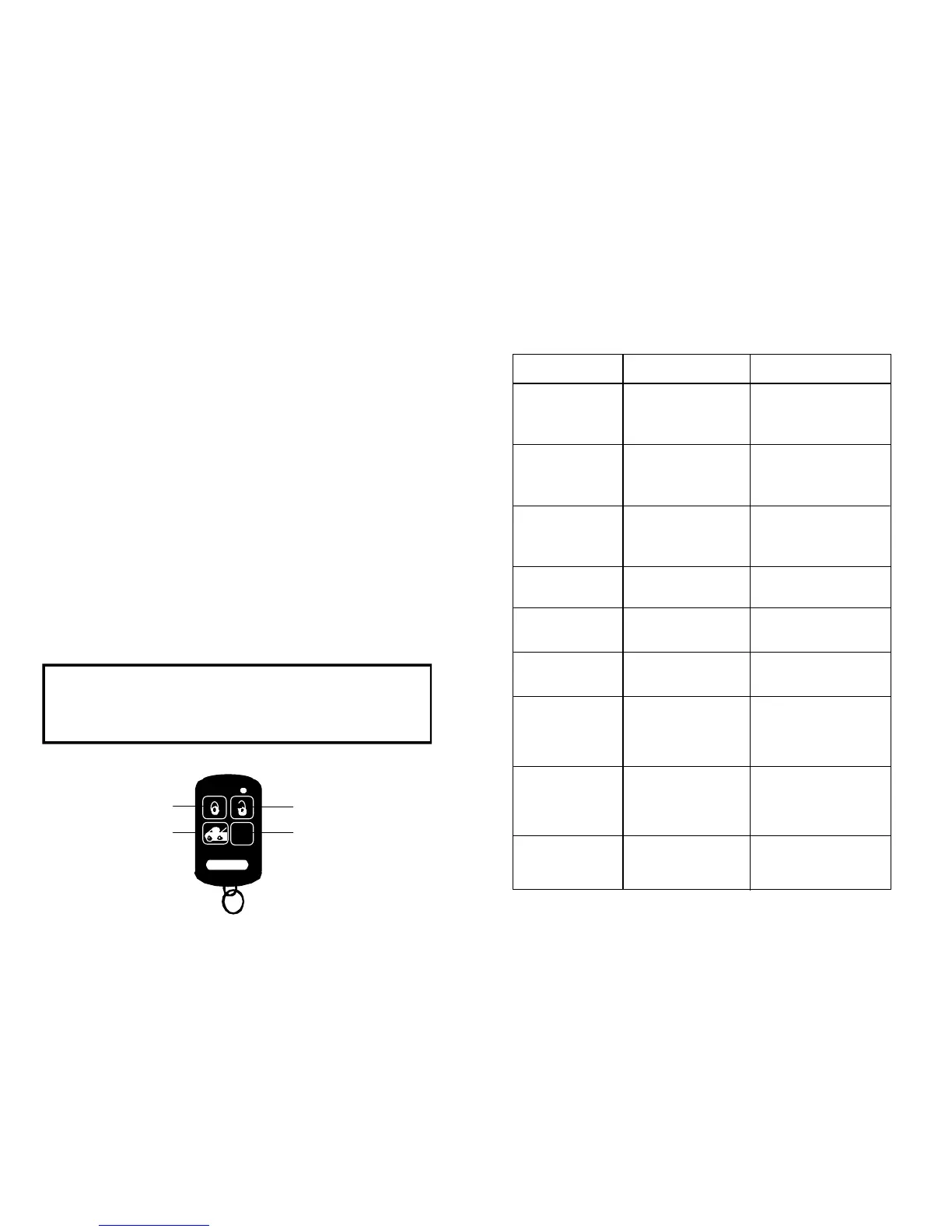
BUTTON #2
BUTTON #4
*
BUTTON #1
BUTTON #3
LOCK
UNLOCK
START
TRUNK
 Loading...