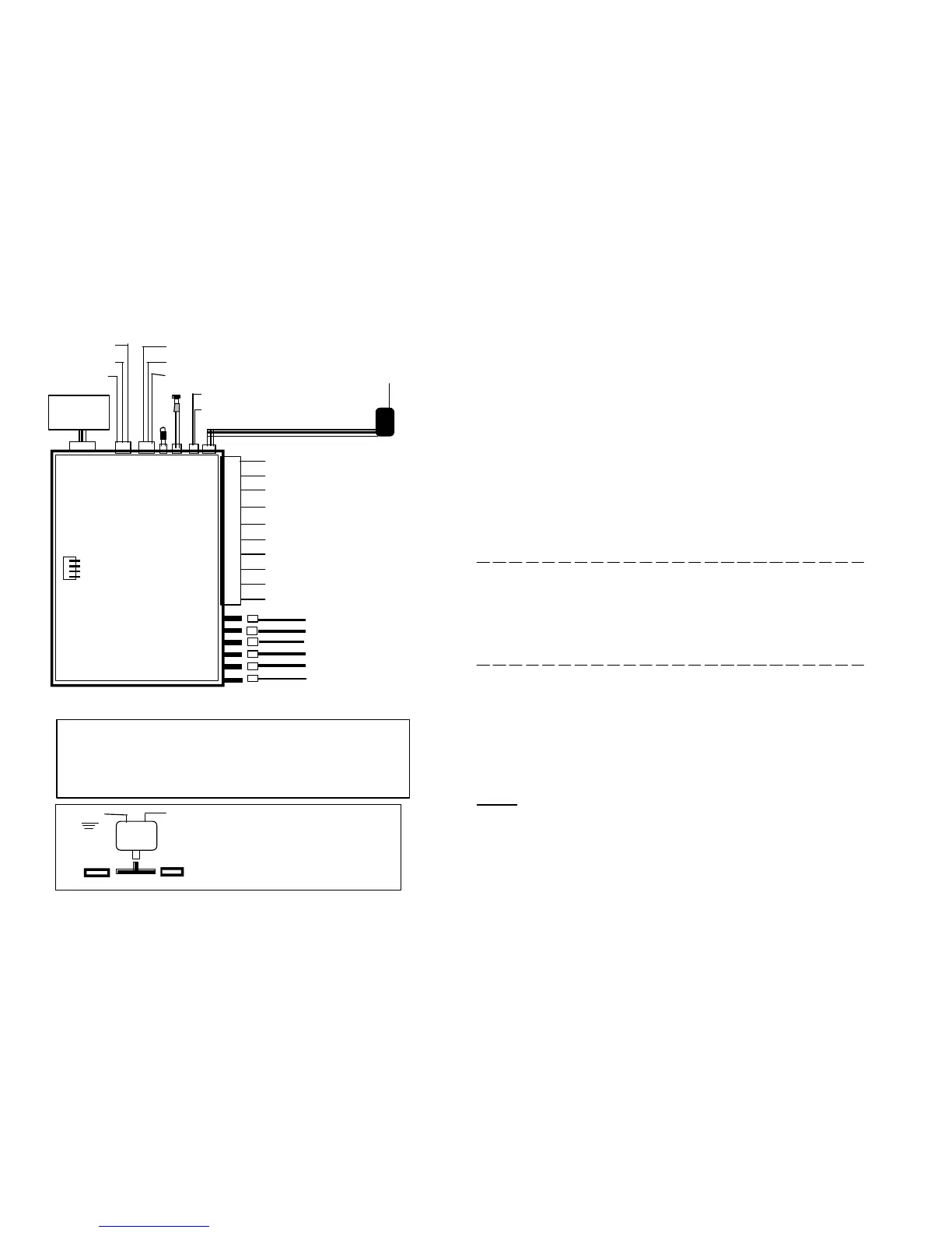
Yellow----Brake Light Switch
Ground
Dip Switchs
FIG. 1
Blue------(-) Trigger
Gray-------Spark Plug Sense
Red -------12V + Battery Power
White-----Parking Lights
Vacuum
Switch
Optional
"YELLOW WIRE"
VACUUM SYSTEM HOOK-UP
FIG. 2
YELLOW
FIG. 1
VACUUM TEE
If Vacuum Hook-Up is required
An additional Vacuum Kit can be added
That includes: Vacuum Switch, Hose,
Vacuum "T", Connectors.
Green-----(-) Door Trigger
White/Yellow -Horn Out (-)
Red/Black -Dome Light (-)
REMOTE ALARM & STARTER WIRING
Brown----Alarm Siren Wire
Black-----Ground
Orange---(-) Armd Output
Violet----(+) Door Trigger
Green/Black -Trunk
Red - Factory Disarm
Yellow - Vacuum Sys. (FIG.2)
Blue - Unlock
Red -12V+ Out
Green - Lock
Shock
Sensor Plug
Violet - Starter
Orange - Accessory
Yellow - Ignition 1
Brown - Ignition 2
Red - 12V + BATTERY
Red - 12V + BATTERY
WHITE:------------
RED:----------------
BROWN:----------
BLACK:-----------
ORANGE:---------
GRAY: -------------
GREEN:------------
BLUE:--------------
VIOLET:-----------
YELLOW:---------
Connect to the (+) side of parking lights.
Connect to Battery constant 12V.+ power.
Connect to the red wire of Siren (+) Output.
Connect to a Good Ground.
Connect to a 30 Amp. Relay for Starter Kill (-) Output.
Wrap around a Any Spark Plug cable or Tachometer.
Door pin (-) Trigger.
Hood pin or extra Sensors (-) Trigger.
Door pin (+) Trigger.
Connect to the Brake light switch (+) when Brake is pressed.
RED: ---------
RED: ---------
BROWN:----
YELLOW:---
ORANGE:---
VIOLET: ----
Connect to Battery constant 12V. (+) POWER.
Connect to Battery constant 12V. (+) POWER.
Connect to Ignition switch #2 if needed.
Connect to Ignition switch wire which is powered 12V.+ even on cranking.
Connect to Ignition switch ACC circuit (Air Cond./Heater).
Connect to Starter wire witch is powered ONLY on cranking position.
65
YELLOW: VACUUM (optional)
A. Find the existing Vacuum Hose at the intake manifold. Cut hose and install the Vacuum
Tee included in the optional kit. (See FIG. 2).
B. Connect to one of the pin on the Vacuum switch , and Ground the other Pin.
Please note that Vacuum Hose other than the manifold and less than 10"
vacuum may cause starter damage.
1- Factory disarm pulse will be activated any time alarm disarms
2- The horn output will trigger with all triggers
3- Door lock when start, Relock when engine shut down
4- Ground output wire will supply ground when starter is engaged no matter if alarm is
armed or disarmed.
NOTE
RF
Receiver
LED
Swtch
DIP SWITCH SETTINGS
4- PIN WHITE CONNECTOR:---------
3- PIN WHITE CONNECTOR:---------
2- PIN RED CONNECTOR:------------
2- PIN BLUE CONNECTOR:----------
2- PIN BLUE CONNECTOR:----------
4- PIN WHITE CONNECTOR:
--------
Plug in Shock Sensor.
Plug in Door Lock Unlock Wire.
Plug in LED and mount in a desirable location.
Plug in PROGRAM/VALET Switch.
Plug in Horn / Dome Light Wire.
Plug in R/F RECEIVER.
MADE IN USA
COMBO
ALARM&START
1-ON= GASOLINE ENGINES
2-ON= NON VACUUM SENSE
3-ON= CRANK TIME NORMAL
4-ON= SMART SENSE
OFF= DIESEL ENGINES
OFF= VACUUM SWITCH SENSE
OFF= CRANK TIME LONGER
OFF= SPARK PLUG OR TACH
 Loading...