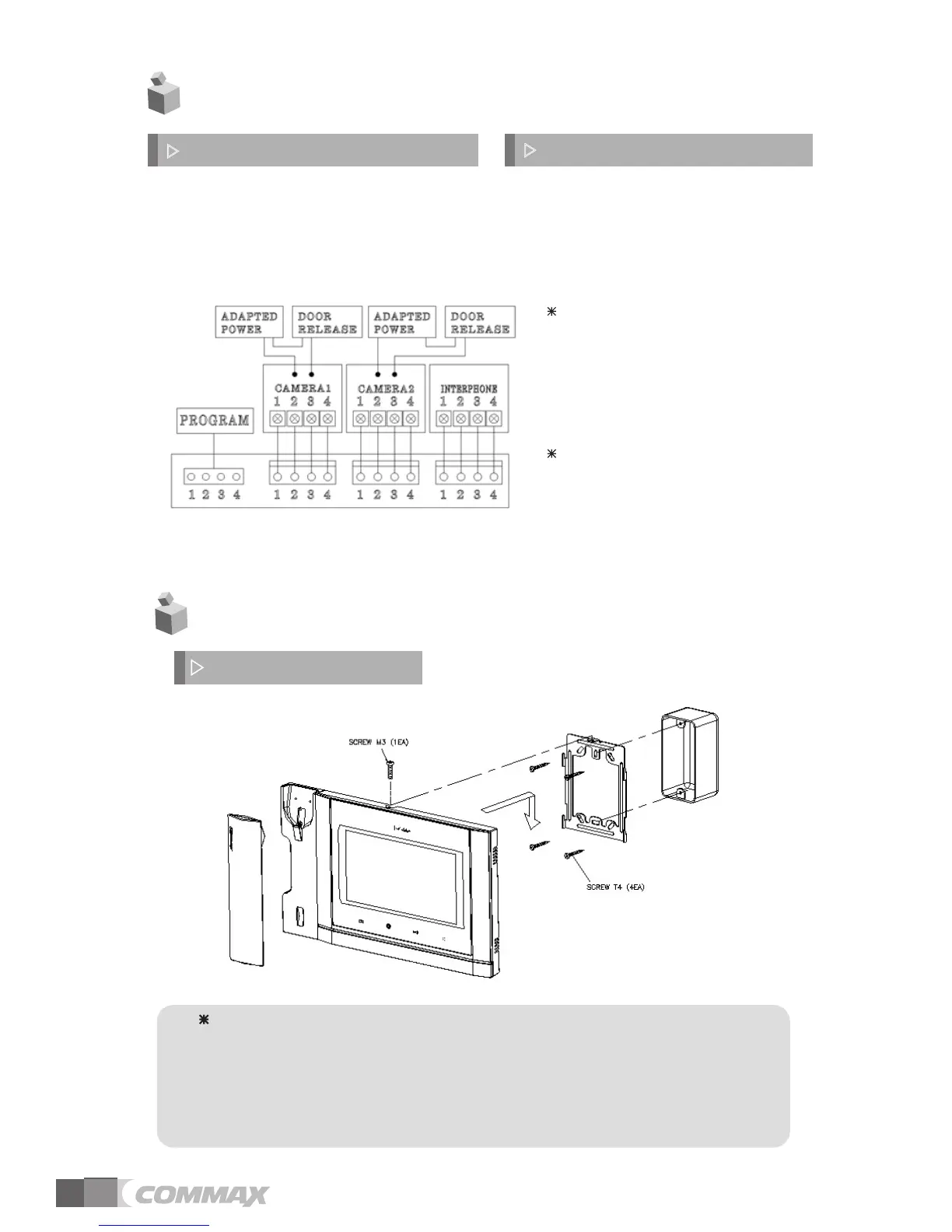
1. Red: Talk (Audio)
2. Blue: GND
3. Yellow: Power (+12V)
4. White: Video
▷
Polarity of the camera connector
1. Red: Talk (Audio)
2. Blue: GND
3. Yellow: Power (+14V)
4. White: Call signal
▷
Polarity of interphone connector
4. Wiring and Connection Instructions
4
4
. Installation
▷
Monitor installat
ion
Note
Avoid installing the produc
t in the area of direct sunlight.•
• The position of the unit's body should fit the standard height range
(Recommended height range is 1450 ~ 1500mm.)
• Avoid installing the product exposed to gas exposure, magnetic force,
in humid temperatures, as it may damage the condition and
performance of the product.
5
Each device should be connected by
If you use UTP CABLE[CAT.5] for
separated cables.
CAMERA1and CAMERA2, 2 lines of
UTP cable are required.
If you use UTP CABLE[CAT.5], connect
4 lines between monitor and interphone.
the rest 4 lines to GND after connecting