4
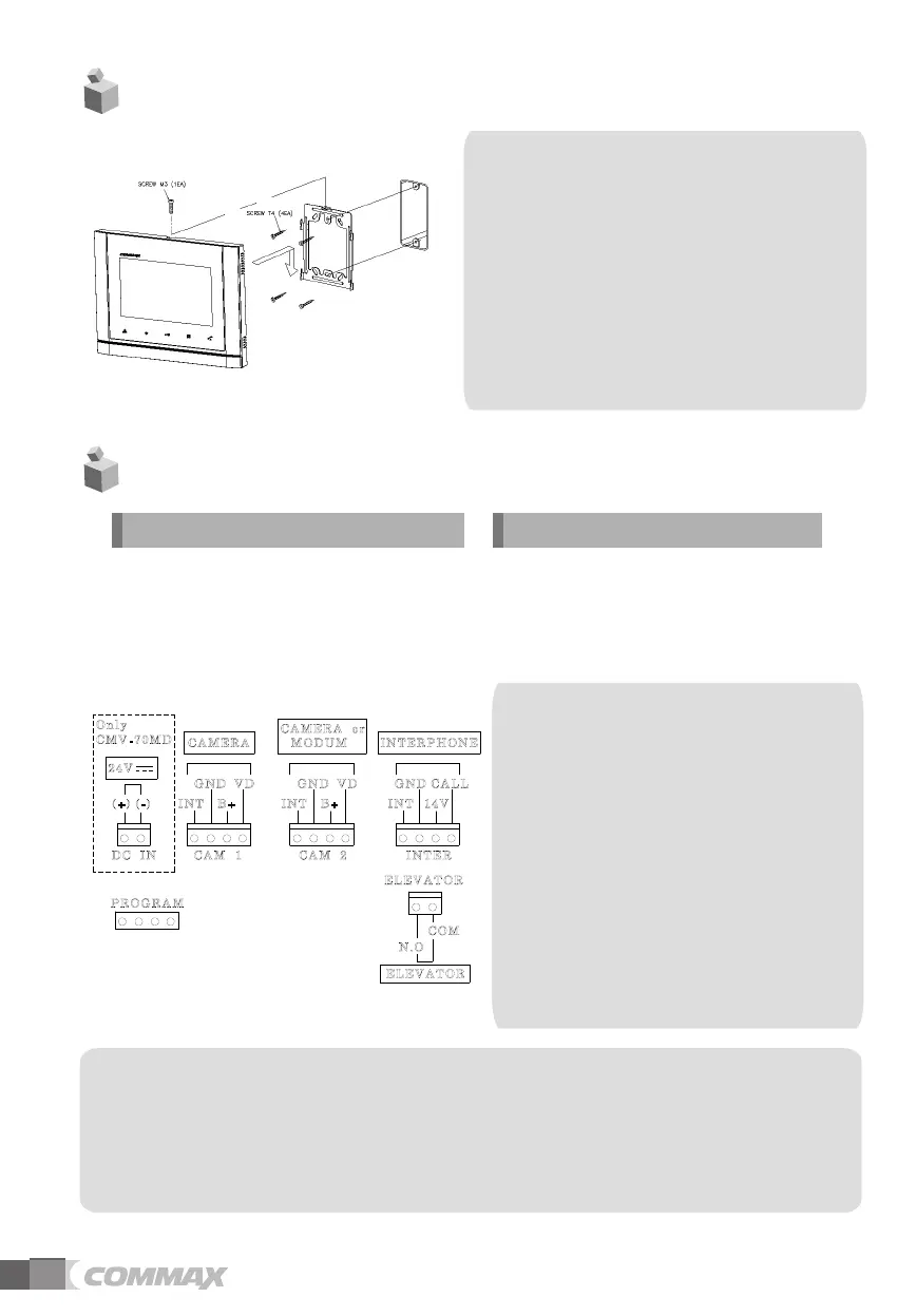
4. Installation
5.Wiring
1. Red: Talk (Audio)
2. Blue: GND
3. Yellow: Power (+12V)
4. White: Video
▷
▷
Polarity of the camera connector
1. Red: Talk (Audio)
2. Blue: GND
3. Yellow: Power (+14V)
4. White: Call signal
▷
▷
Polarity of interphone connector
※
Note
1. In case, if there is a high-voltage power line in the area of installation, use metal tube
coaxial cable for wiring
2. Beware of wrinkling of line coating and cable stick-outs as it may cause circuit shortage
and
operation
inconvenience.
3. When connecting a monitor with a camera, make sure power switch is turned off.
Note
•
•
•
performance of the product.
Avoid installing the product in
the area of direct sunlight.
The position of the unit's body should
fit the standard height range
Avoid installing the product exposed to
gas exposure, magnetic force,
in humid temperatures, as it may
damage the condition and
(Recommended height range is
1450 ~ 1500mm.)
Warning :
-
distributor, it will not be operated normally.
If you connect with MODUM system, you need
to connect with 'CAMERA2' ports and
floor distributor(Please refer to the manual of
floor distributor for wiring.)
If you connect with a floor distributor(to connect
with lobby or guard station), you have
to connect with only 'CAMERA2' port.(If you
connect with 'CAMERA1' port and floor
- Do not use it with other devices when you use it
with floor distributor, other devices,
-
When the system power cut off in case of blackout,
each device can't be recognized to
each other because of communication problem.
In this case, re-boot the Video-phone.