Do you have a question about the Commax TP–nKP and is the answer not in the manual?
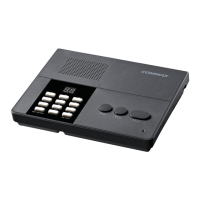
Details the step-by-step process for wiring and configuring the system.
Connectors are wired in parallel, excluding specific terminals.
Wiring for the first interphone, connecting '1' to 'L' and shorting 'P' and '1'.
Wiring for the second interphone, connecting '2' to 'L' and shorting 'P' and '2'.
Wiring for the tenth interphone, connecting '10' to 'L' and shorting 'P' and '10'.
Cable length limit to ensure proper system operation.
Low voice or no sound issue troubleshooting.
Issue with calling specific interphones.
Troubleshooting a malfunctioning unit.
| Brand | Commax |
|---|---|
| Model | TP–nKP |
| Category | Intercom System |
| Language | English |