1930 SERVICE MANUAL
¥
specified value and that it is regulated correctly.
W e suggest that you and your service techni
cians review test procedures so that HV and HV
regulation are always checked as a standard
servicing procedure, and the reason for this pru
dent routine be clearly understood by everyone.
It is important to use an accurate and reliable
HV meter. It is recommended that the HV read
ing be recorded on each customers' invoice,
which will demonstrate a proper concern for the
customers' safety.
5. When troubleshooting and making test meas
urements in a receiver with a problem of ex
cessive high voltage, reduce the line voltage by
means of a Variac to bring the HV into accep
table limits while troubleshooting. Do not oper
ate the chassis longer than necessary to locate
the cause of the excessive HV.
6. New type picture tubes are specifically designed
to withstand higher operating voltages without
creating undesirable X-radiation. It is strongly
recommended that any shop test fixture which
is to be used with the new higher voltage
chassis be equipped with one of the new type
tubes designed for this service. Addition of a
permanently connected HV meter to the shop
test fixture is advisable. The CRT types used
in these new sets should never be replaced with
any other types, as this may result in excessive
X-radiation.
7. It is essential to use the specified picture tube
to avoid a possible X-radiation problem.
8. Most TV receivers contain some type of emer
gency “ Hold Dow n" circuit to prevent HV from
rising to excessive levels in the presence of a
failure mode. These various circuits should be
understood by all technicians servicing them,
especially since many hold down circuits are
inoperative as long as the receiver performs
normally.
Leakage Current Cold Check
1. Unplug the ac line cord and connect a jumper
between the tw o prongs of the plug.
2. Turn on the power switch.
3. Measure the resistance value between the
jumpered ac plug and all exposed cabinet parts
of the receiver, such as screw heads, antennas
and control shafts. When the exposed metallic
part has a return path to the chassis, the reading
should be between 1 megohm and 5.2 meg
ohms. When the exposed metal does not have
a return path to the chassis, the reading must
be infinity. Remove the jumper from the ac line
cord.
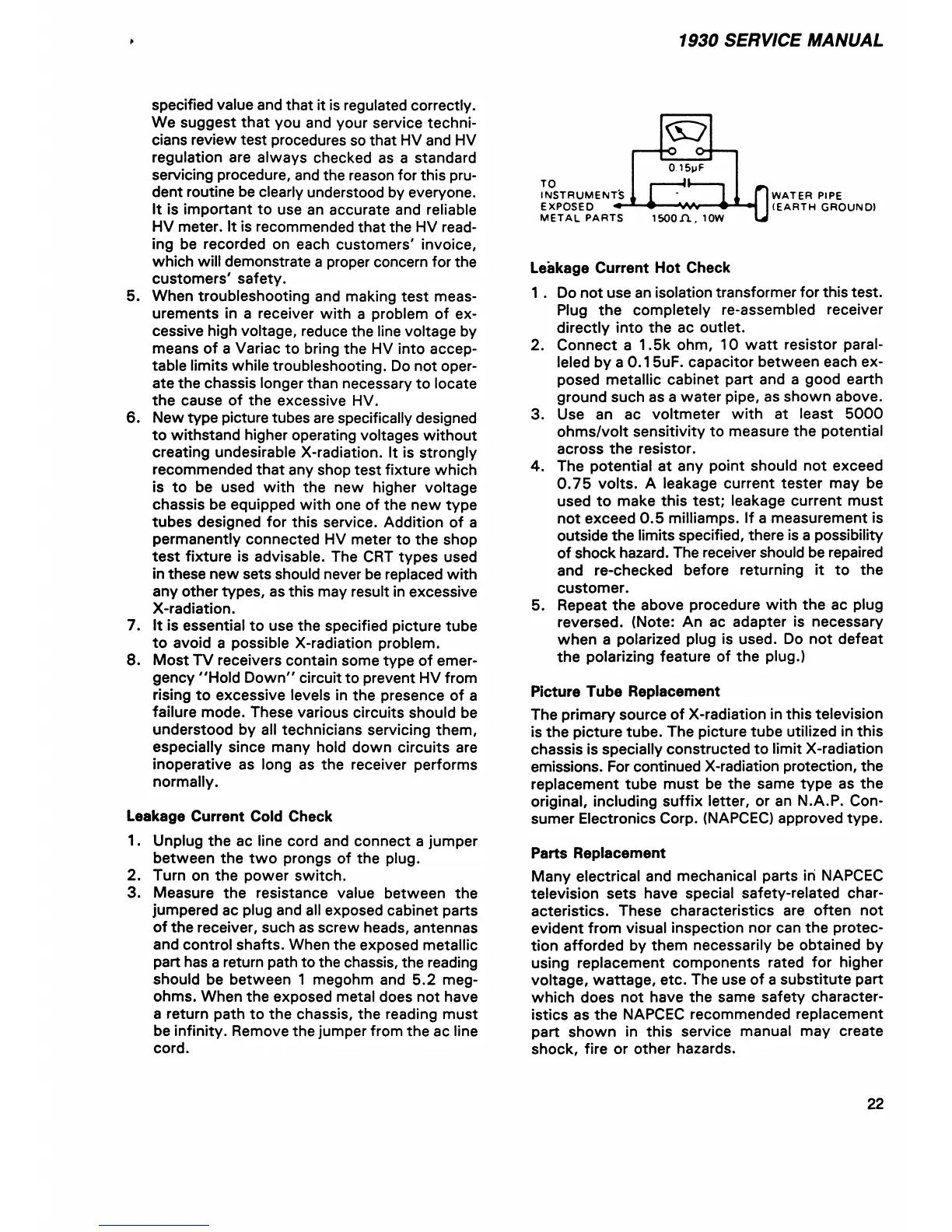
Leakage Current Hot Check
1 . Do not use an isolation transformer for this test.
Plug the completely re-assembled receiver
directly into the ac outlet.
2. Connect a 1.5k ohm, 10 w att resistor paral
leled by a 0 .1 5uF. capacitor between each ex
posed metallic cabinet part and a good earth
ground such as a water pipe, as shown above.
3. Use an ac voltmeter with at least 5000
ohms/volt sensitivity to measure the potential
across the resistor.
4. The potential at any point should not exceed
0.7 5 volts. A leakage current tester may be
used to make this test; leakage current must
not exceed 0 .5 milliamps. If a measurement is
outside the limits specified, there is a possibility
of shock hazard. The receiver should be repaired
and re-checked before returning it to the
customer.
5. Repeat the above procedure with the ac plug
reversed. (Note: An ac adapter is necessary
when a polarized plug is used. Do not defeat
the polarizing feature of the plug.)
Picture Tube Replacement
The primary source of X-radiation in this television
is the picture tube. The picture tube utilized in this
chassis is specially constructed to limit X-radiation
emissions. For continued X-radiation protection, the
replacement tube must be the same type as the
original, including suffix letter, or an N.A.P. Con
sumer Electronics Corp. (NAPCEC) approved type.
Parts Replacement
Many electrical and mechanical parts in NAPCEC
television sets have special safety-related char
acteristics. These characteristics are often not
evident from visual inspection nor can the protec
tion afforded by them necessarily be obtained by
using replacement components rated for higher
voltage, w attage, etc. The use of a substitute part
which does not have the same safety character
istics as the NAPCEC recommended replacement
part shown in this service manual may create
shock, fire or other hazards.
TO
INSTRUMENT'S
EXPOSED
METAt PARTS
isoon. iow
0
WATER PIPE
(EARTH GROUND)
22