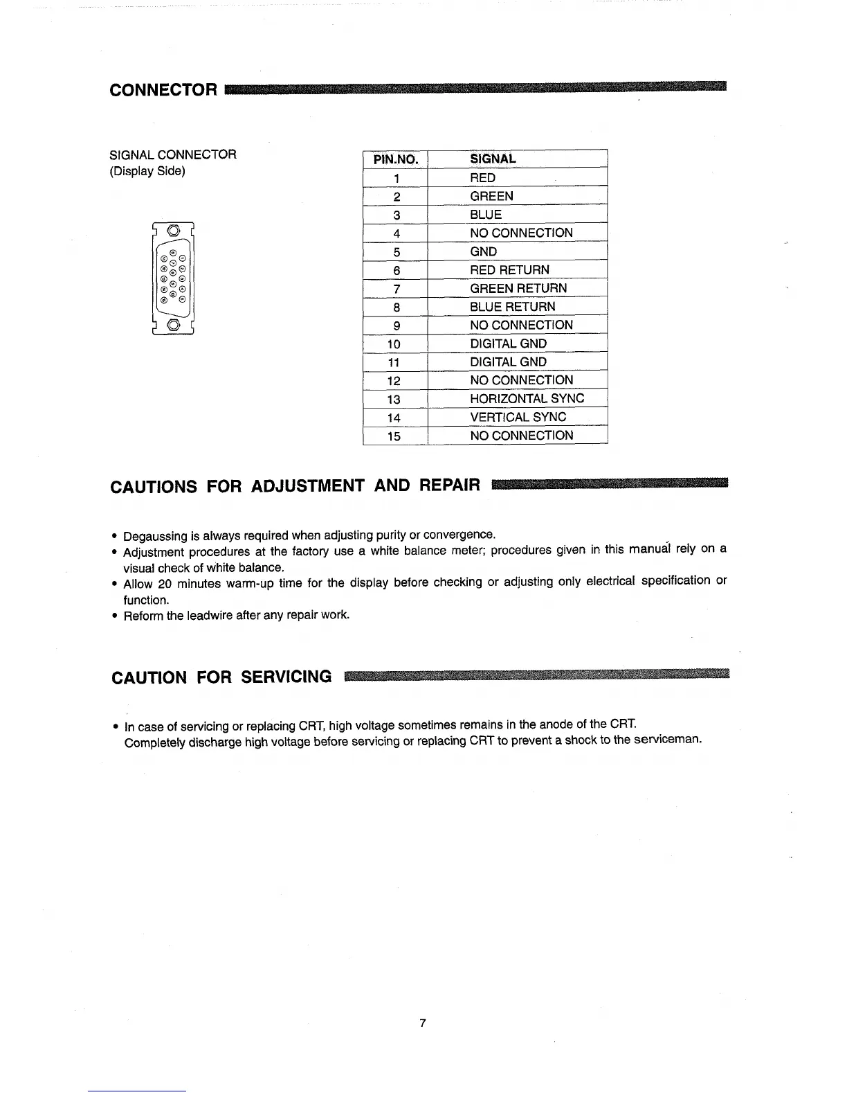
SIGNAL CONNECTOR
(Display Side)
I
PIN.NO.
1
2
3
4
5
6
7
8
9
10
11
12
13
14
15
SIGNAL
RED
GREEN
BLUE
NO CONNECTION
GND
RED
RETURN
GREEN RETURN
BLUE RETURN
NO CONNECTION
DIGITALGND
DIGITALGND
NO CONNECTION
HORIZONTAL SYNC
VERTICAL SYNC
NO CONNECTION
I
CAUTIONS
FOR
ADJUSTMENT
AND
REPAIR
• Degaussing is always required when adjusting purity or convergence.
I
• Adjustment procedures at the factory use a white balance meter; procedures given in this manual rely on a
visual check of white balance.
• Allow 20 minutes warm-up time for the display before checking or adjusting only electrical specification or
function.
• Reform the leadwire after any repair work.
CAUTION FOR SERVICING
•
In
case of servicing or replacing
CRT,
high voltage sometimes remains in the anode of the
CRT.
Completely discharge high voltage before servicing or replacing CRT to prevent a shock to the serviceman.
7