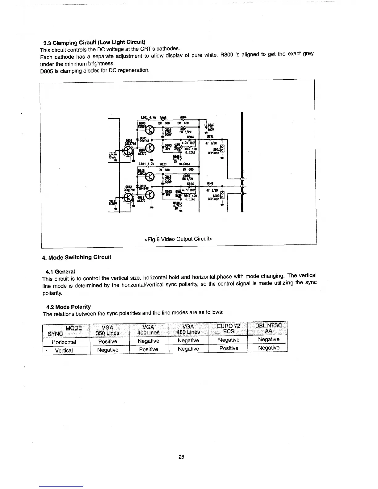
3.3 Clamping Circuit (Low Light Circuit)
This circuit controls the
DC
voltage
at
the CRT's cathodes.
Each cathode has a separate adjustment to allow display of pure white.
RB09
is
aligned to get the exact grey
under the minimum brightness.
DB05
is
clamping diodes for
DC
regeneration.
<Fig.B Video Output Circuit>
4.
Mode
Switching Circuit
4.1
General
This circuit
is
to control the vertical size, horizontal hold and horizontal.phase with mode changing. The vertical
line mode
is
determined by the horizontal/vertical sync
pOliarity,
so
the
control signal
is
made utilizing the sync
poliarity.
4.2 Mode Polarity
The relations between the sync polarities and the line modes are
as
follows:
MO.D~
VGA.··
VGA
VGA
E'JR01~
QaLNTSC
SyNC
35g
LinE!~
40pLines
4BO
Lines
ECS
AA
..
..
Horizontal Positive Negative Negative Negative
Negative
Vertical Negative
Positive
Negative Positive
Negative
26