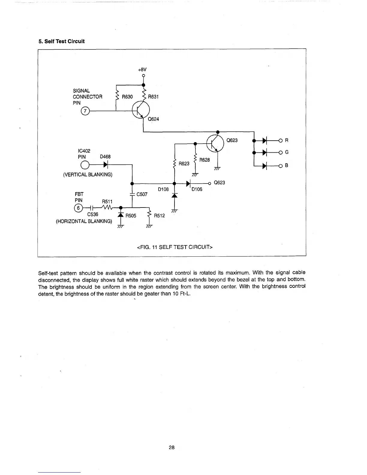
5. Self Test Circuit
SIGNAL
CONNECTOR
PIN
IC402
PIN
0468
(VERTICAL
BLANKING)
FBT
PIN
@--i
C536
(HORIZONTAL
BLANKING)
+8V
0623
_ ......
--oR
_ ......
--oG
R623
'---.t---o
B
_----~J--I*--__o
0623
0108 0106
I
R512
<FIG.
11
SELF TEST CIRCUIT>
Self-test pattern should be available when the contrast control
is
rotated its maximum. With the signal cable
disconnected, the display shows full white raster which should extends beyond the bezel at the top and bottom.
The brightness should
be
uniform
in
the region extending from
the
screen center. With the brightness control
detent, the brightness of the raster should be geater than
10 Ft-L.
28