This amplitude of blanking pulse
can
be
adjusted by voltage applied to terminal 20 of
TA8631
N.
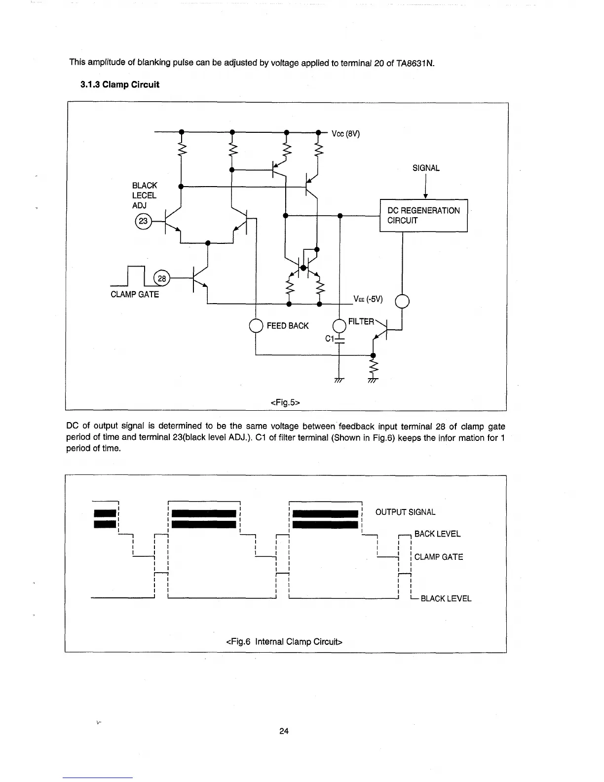
3.1.3 Clamp Circuit
--
.....
---
.....
---~J--
....
-
Vee
(8V)
SIGNAL
1
BLACK
LECEL
ADJ
DC
REGENERATION
CIRCUIT
'--
___
+-
__
....
--4I>---+-VEE
(-5V)
FEED
BACK
<Fig.5>
DC
of output signal is determined to
be
the same voltage between feedback input terminal 28
of
clamp gate
period
of
time and terminal 23(black level ADJ.).
C1
of
filter terminal (Shown
in
Fig.6) keeps the infor mation for 1
period
of
time.
----.
r'----------~,
,r------------"
_:
:
::
:
OUTPUT
SIGNAL
-:
: : : :
~
ri
~
ri
~
1"1
BACK
LEVEL
I I I I I I I I I
I I I I I I I I I
~
:
!....-..i
:
~
:
CLAMP
GATE
I I I I I I
I I I I I I
r--1
,--1
1"1
I I I I I I
I I I I I I
I I I I I I
________
---',
, I I I
L.
BLACK
LEVEL
<Fig.6 Internal Clamp Circuit>
24