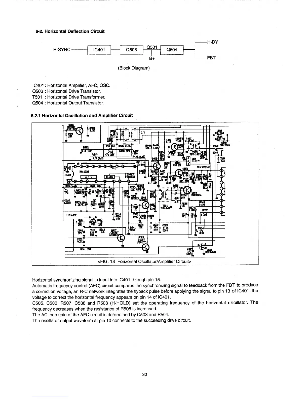
6·2. Horizontal Deflection Circuit
H-SYNC
----j
0501
I
IC401 H
0503
B+
~
H-DY
0504
L-
__
-.l
FBT
(Block Diagram)
IC401
: Horizontal Amplifier, AFC, OSC.
0503
: Horizontal Drive Transistor.
T501
: Horizontal Drive Transformer.
0504
: Horizontal Output Transistor.
6.2.1 Horizontal Oscillation and Amplifier Circuit
<FIG. 13 Forizontal Oscillator/Amplifier Circuit>
Horizontal synchronizing signal is input into
IC401
through pin
15.
Automatic frequency control (AFC) circuit compares the synchronizing signal to feedback from the
FBT
to produce
a correction
voltage, an
R-C
network integrates the flyback pulse before applying the signal to pin 13
of
IC401. the
voltage to correct the horizontal frequency appears
on
pin 14 of IC401.
C505, C506, R507, C538 and R508 (H-HOLD) set the operating frequency of the horizontal oscillator. The
frequency decreases when the resistance of R508 is increased.
The AC loop gain of the AFC circuit
is
determined by C503 and R504.
The oscillator output
waveform at pin 10 connects to the succeeding drive circuit.
30