The voltage is regulated controlling the positive bias of TR1.
A larger collector
curr~nt
is required to turn off TR2
if
the base is fully biased.
Therefore, more energy is stored by the primary winding of 1-3 of T001. The collector current of TR3 required to
turn off TR2 is reduced when the above gate
is
slightly biased, and less energy is stored
in
the winding 4-2.
The voltage (comparative to the output voltage) induced while TR3 is being kept off is rectified via 01, and it is
used by the voltage regulator.
When the output voltage is raised by an increase in the input voltage or a decrease
in
the load, the emitter voltage
of
TR1
rises to turn off
TR1
so as to take down the voltage at the base of TR2, thus TR2 is turned off and base
voltage of TR3
is
decreased.
Hence the energy stored in the winding 1-3 is reduced and the output voltage is
in
turn lowered.
When the output voltage of
TR1
is decreased, a larger collector current through TR3 turns on
TR1
and TR2.
Consequently more energy is stored
in
the winding 1-3 which increased the output voltage.
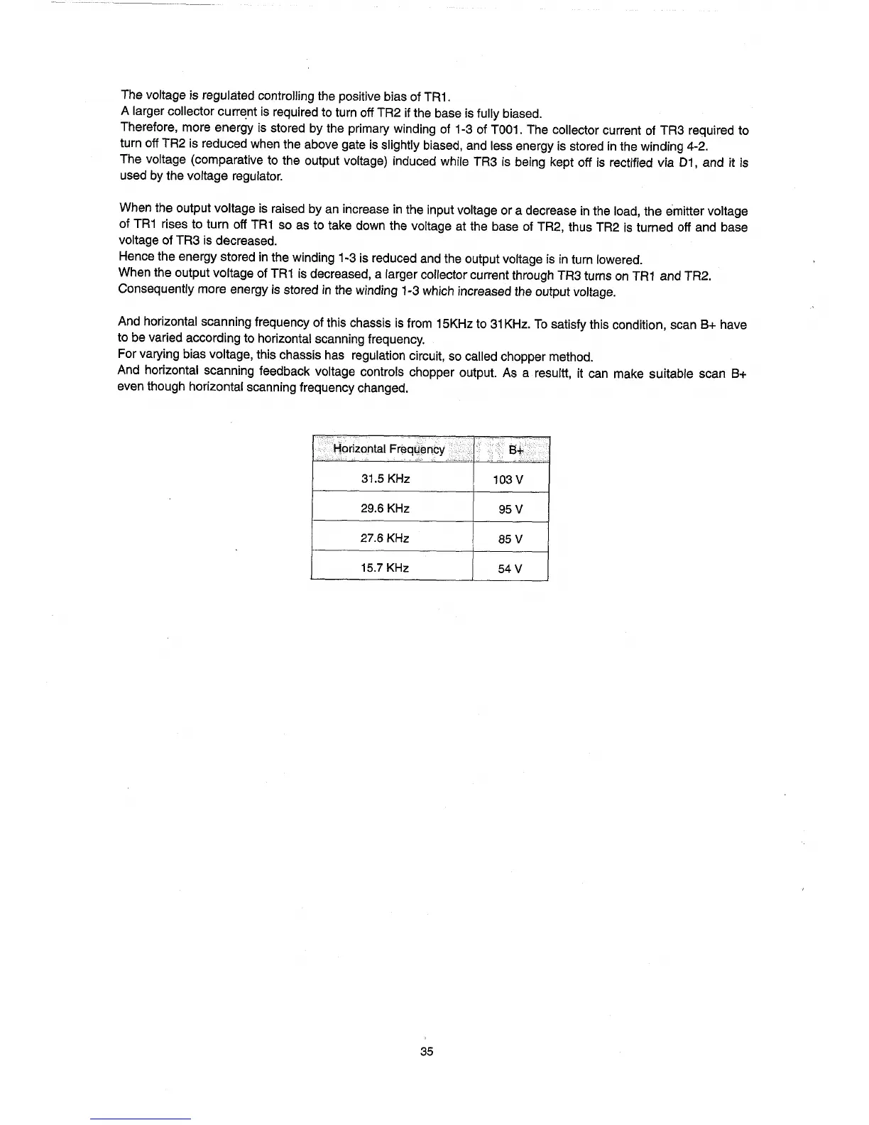
And horizontal scanning frequency of this chassis
is
from 15KHz to
31
KHz.
To
satisfy this condition, scan B+ have
to be varied according to horizontal scanning frequency.
For varying bias voltage, this chassis has regulation circuit, so called chopper method.
And horizontal scanning feedback voltage controls chopper output.
As
a resultt,
it
can make suitable scan
B+
even though horizontal scanning frequency changed.
I··~···
Horizontal Freauencv
,.
.
31.5 KHz
103 V
29.6 KHz
95V
27.6 KHz
85 V
15.7 KHz 54 V
35