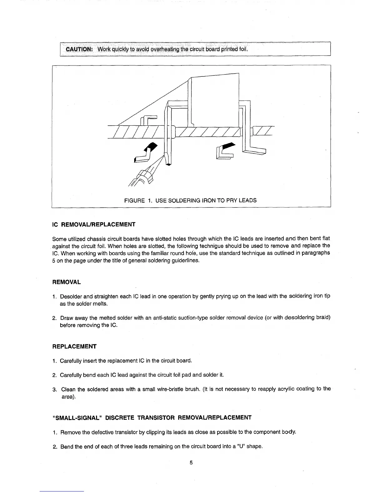
FIGURE
1.
USE SOLDERING IRON TO PRY LEADS
IC REMOVAUREPLACEMENT
Some utilized chassis circuit boards have slotted holes through which the IC leads are inserted
and
then bent flat
against the circuit foil. When holes are slotted, the following technigue should be used to remove and replace the
IC.
When working with boards using the familiar round hole, use the standard technique as outlined in paragraphs
5 on the page under the title of general soldering guiderlines.
REMOVAL
1.
Desolder and straighten each
IC
lead
in
one operation by gently prying
up
on
the lead with the soldering iron tip
as the solder melts.
2.
Draw away the melted solder with an anti-static suction-type solder removal device (or with desoldering braid)
before removing the IC.
REPLACEMENT
1.
Carefully insert the replacement
IC
in
the circuit board.
2.
Carefully bend each IC lead against the circuit foil pad and solder
it.
3.
Clean the soldered areas with a small wire-bristle brush. (It is not necessary to reapply acrylic coating to the
area).
"SMALL-SIGNAL" DISCRETE TRANSISTOR REMOVAUREPLACEMENT
1.
Remove the defective transistor by clipping its leads as close as possible to the component body.
2.
Bend the end of each of three leads remaining
on
the circuit board into a "U" shape.
5