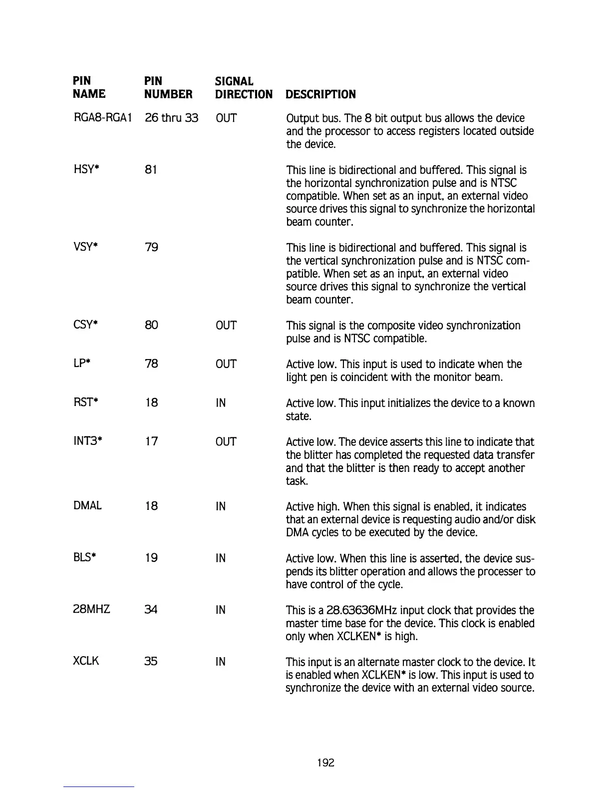
PIN PIN SIGNAL
NAME NUMBER DIRECTION DESCRIPTION
RGA8-RGA1 26 thru
33
OUT Output bus. The
8
bit output bus allows the device
and the processor to access registers located outside
the device.
HSY*
8
1
VSY
*
79
CSY
*
80
OUT
LP*
78
OUT
RST* 18
IN
I
NT3* 17 OUT
DMAL
18
IN
BLS*
19
IN
28M HZ
34
IN
XCLK
35
IN
This line is bidirectional and buffered. This signal is
the horizontal synchronization pulse and is NTSC
compatible. When set as an input, an external video
source drives this signal to synchronize the horizontal
beam counter.
This line is bidirectional and buffered. This signal is
the vertical synchronization pulse and is NTSC com-
patible. When set as an input, an external video
source drives this signal to synchronize the vertical
beam counter.
This signal is the composite video synchronization
pulse and is NTSC compatible.
Active low. This input is used to indicate when the
light pen is coincident with the monitor beam.
Active low. This input initializes the device to a known
state.
Active low. The device asserts this line to indicate that
the blitter has completed the requested data transfer
and that the blitter is then ready to accept another
task.
Active high. When this signal is enabled,
it
indicates
that an external device is requesting audio
andlor disk
DMA
cycles to be executed by the device.
Active low. When this line is asserted, the device sus-
pends its blitter operation and allows the processer to
have control of the cycle.
This is a
28.63636MHz input clock that provides the
master time base for the device. This clock is enabled
only when XCLKEN* is high.
This input is an alternate master clock to the device.
It
is enabled when XCLKEN* is low. This input is used to
synchronize the device with an external video source.