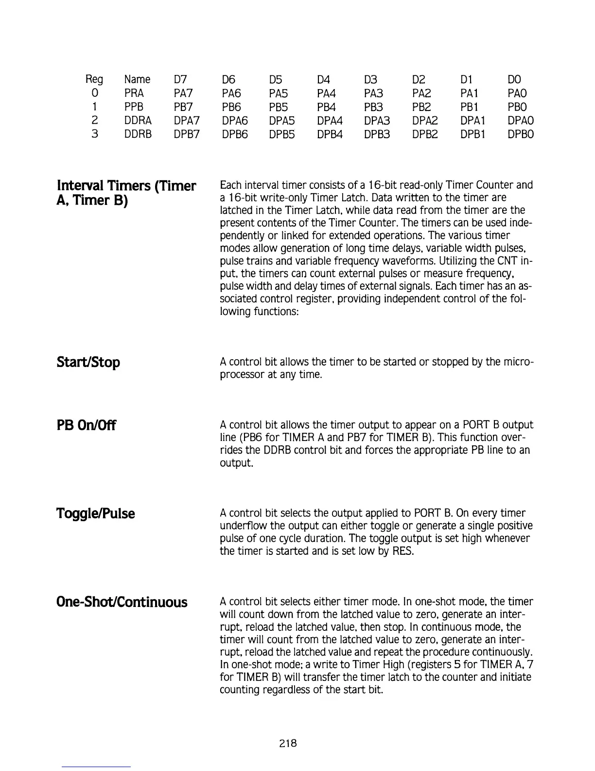
Reg Name D7 D6 D5 D4
D3
D2 D 1 DO
0
PRA
PA7 PA6
PA5 PA4
PA3
PA2
PA 1 P A0
1
PPB
PB7 PB6
PB5 P
B4
PB3
PB2 PB1 PBO
2 DDRA
DPA7
DPA6
DPA5 DPA4 DPA3
DPA2 DPAl DPAO
3
DDRB DPB7
DPB6 DPB5 DPB4
DPB3 DPB2
DPBl DPBO
Interval Timers (Timer
Each interval timer consists of a 16-bit read-only Timer Counter and
A,
Timer
B)
a 16-bit write-only Timer Latch. Data written to the timer are
latched in the Timer Latch, while data read from the timer are the
present contents of the Timer Counter. The timers can be used inde-
pendently or linked for extended operations. The various timer
modes allow generation of long time delays, variable width pulses,
pulse trains and variable frequency waveforms. Utilizing the CNT in-
put, the timers can count external pulses or measure frequency,
pulse width and delay times of external signals. Each timer has an as-
sociated control register, providing independent control of the fol-
lowing functions:
A control bit allows the timer to be started or stopped by the micro-
processor at any time.
A control bit allows the timer output to appear on a PORT B output
line (PB6 for TIMER A and PB7 for TIMER B). This function over-
rides the DDRB control bit and forces the appropriate PB line to an
output.
A control bit selects the output applied to PORT B. On every timer
underflow the output can either toggle or generate a single positive
pulse of one cycle duration. The toggle output
is
set high whenever
the timer is started and
is
set low by RES.
One-S~O~/CO~~~~UOUS
A
control bit selects either timer mode. In one-shot mode, the timer
will count down from the latched value to zero, generate an inter-
rupt, reload the latched value, then stop. In continuous mode, the
timer will count from the latched value to zero, generate an inter-
rupt, reload the latched value and repeat the procedure continuously.
In one-shot mode; a write to Timer High (registers
5
for TIMER
A,
7
for TIMER
B)
will transfer the timer latch to the counter and initiate
counting regardless of the start bit.