17.
CONVERGENCE
ADJUSTMENTS
NOTE:
Before attempting any
convergence
adjustments, the
receiver should
be
operated for at least fifteen minutes.
Contre
Convergence
Adjustment
1. Supply crosshatch pattern with a color
bar
signal generator
to the video Input.
2. Adjust the BRIGHTNESS
and
CONTRAST Controls for well
defined pattern
3. Adjust two tabs
of
the 4-Pole
Magnets
to
change
the angle
between them (See figure 2)
and
superimpose red
and
blue
vertical lines
in
the center area of the picture screen. (See
figure 2)
4. Turn the both tabs at the same time keeping the angel constant
to superimpose red and blue hOrizontal lines at the centre of
the screen. (See figure 3)
5.
Adjust two tabs of 6-Pole
Magnets
to superimpose red/blue
line
and
green one. adjusting the angle affects the vertical lines
and rotating
both
magnets
affects the hOrizontal lines.
6.
Repeat adjustments 3.4,5 with understanding red, green
and
blue movement. because 4-Pole Magnets and 6-Pole Magnets
have mutual affection
and
it
makes dots movement complex
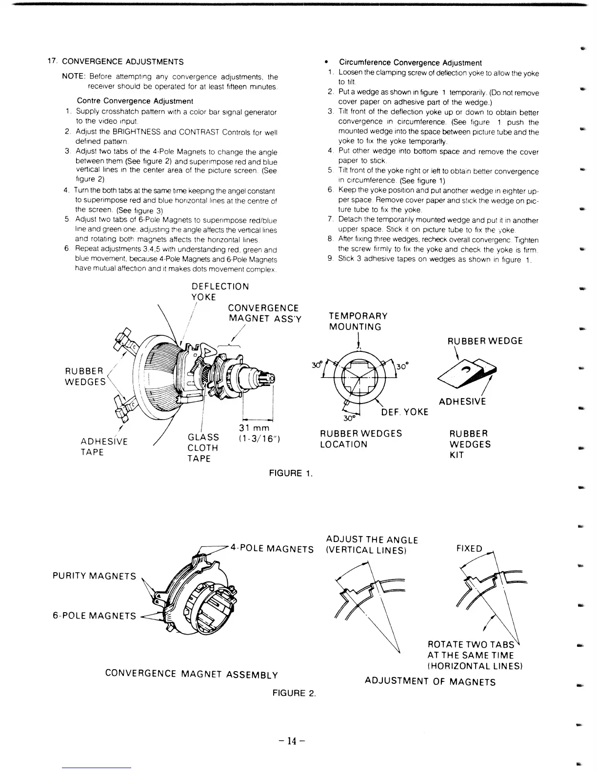
RUBBER
WEDGES
ADHESIVE
TAPE
DEFLECTION
YOKE
GLASS
CLOTH
TAPE
CONVERGENCE
MAGNET
ASS'Y
/
31
mm
(1-3/16")
FIGURE
1.
•
Circumference
Convergence
Adjustment
1.
Loosen the clamping screw of deflection yoke to allow the yoke
to
tilt
2.
Put a wedge as shown
in
figure 1 temporarily. (Do not remove
cover
paper
on adhesive part of the wedge.)
3.
Tilt front of the deflection yoke
up
or
down
to obtain better
convergence
In
circumference. (See figure
1
push
the
mounted
wedge
into the space between picture tube
and
the
yoke to
fiX
the yoke temporarily.
4.
Put other
wedge
into bottom space and remove the
cover
paper to stick.
5.
Tilt front of the
yoke
right or left to obtain better
convergence
in
circumference. (See figure 1)
6.
Keep the yoke position
and
put another
wedge
in
elghter up-
per space. Remove cover paper
and
stick the
wedge
on
PiC-
ture
tube
to fix the yoke.
7.
Detach the temporarily mounted
wedge
and
put
it
in
another
upper
space. Stick
it
on picture tube to fix the yoke
8.
Atter fixing three wedges, recheck overall convergenc. Tighten
the screw firmly to fix the yoke and
check
the yoke
is
firm.
9.
Stick 3 adhesive tapes on wedges as shown
in
figure
1.
TEMPORARY
MOUNTING
1
RUBBER
WEDGE
\
<Yt
ADHESIVE
RUBBER
WEDGES
LOCATION
RUBBER
WEDGES
KIT
ADJUST
THE
ANGLE
r-----:;;;>""4-POLE
MAGNETS
(VERTICAL LINES)
PURITY
MAGNETS
6-POLE
MAGNETS
CONVERGENCE
MAGNET
ASSEMBLY
FIGURE
2_
-14
-
ROTATE
TWO
TABS
AT THE
SAME
TIME
(HORIZONTAL
LINES)
ADJUSTMENT
OF
MAGNETS
.,
..,
....
-
-
-
..
-
-
-
-