, ............ ------------------.... --------------------.......
----
....
--_
...
_ ........
----
......
----~--
............
--
CIRCUIT DESCRIPTIONS
1, POWER
SUPPLY
This Monitor
power
supply
IS
switching
mode
power
supply (SMPS)
that
is
consist of sWitching
IC
(IC901), SMPS TRANSFORMER
(TOO
1 )
pulse TRANSFORMER (T902) and assoCiated
component
The
BasIC
theory of the SMPS
IS
the circuit of Blocking Oscillation
and
by
tur'
ning ON, OFF of STRA470A. the secondary of the SMPS TRANS
is
applied
the pulse, Instant + 115V DC that pulse
is
rectlflred
IS
abtalns.
All other operating voltage and pulse are
drlved
from the
secondary
winding
of
the
high
voltage transformer (also
called FBT. T703)
2.
ST
Mn
UP
CIRCUIT
An
Initial start·up Circuit provides drive to the horlzontlal output stage
when
the set
IS
Initially turned on
ThiS
CIrcUIt
consists of
0703
and associated components
It
proveds
the Initial voltage necessary to activate IC701
and
pro·
vldes a drive pulse to the hOrizontal drive transistor
0701
Once
the FBT·drived voltages operational
0708
IS
forward· biased
and
0701
is
reverse-biared. prOViding + 45V DC
to
IC701 and 0701
SWitching voltage
supply
CirCUit
like
tr,IS
results
In
saving
power
consumption
3.
HORIZONTAL
DEFLECTION
SYNCHRONIZATION
AND
VERTICAL
Integrated Circuit IC701 perlorms the hOflzontal synchronIZation (also
called horizontal oscl'lator)
A hOrizontal rate output pulse
IS
coupled
from IC701 pin 15
to
hOrlzontai driver
0701.
The driver stage dflves the hOflzorltai out
put
0702.
HOrizontal synchronization slg'1al
IS
derived fronc composite v'deo
Signal which
coupled
to
IC701
pin
10.
Vertical synchronization signal
'5 derived from composite signal at
IC701 pin 8
and
coupled
to
pin 7 through R601
4.
HORIZONTAL
AFC
AND
OSCILLATION
LlMITIER
AFC Circuit
IS
conSists ot phase detection
CirCUit
of IC701 and
0704.
associated
component
Oscillation
limiT
CirCUit
.s
necessarv to
P'8-
vent from excessive high voltage.
ThiS
CirCUit
IS
located
In
IC70
1
and
controls the
OSCillator
to maintain the control signal
In
correct
frequency
and
phase w'th the hOfllonta' sync signal
5.
X-RAY
PROTECTION
CIRCUIT
Hle
X-ray protection
CIiCUltlS
consists
of
0703.
R731
(Hold. Down)
R729. R730
and
assoCiated
ccmponent
that connected to
pl'l
16
of IC701
A pulse
j'om
~BT
Pl~i
6 is rectified by
0705
Under nor-
mal operating condlt!OrlS. tne resui'a'lt voltage maintains
at
specified
value
If
a rna!f,mctlon causes excessive nigh
vOltage.
me
amplitude of pulse
from FBT Increases. cauSing a
corresponding
Increase
In
0703
which
results
In
vos!tage Increase at pin 16 of IC701. Voltage
In-
crease
at
IC701 pin 16 makes
Xray
protection cirCUit
conduct
and
hOrizontal oscliatlon operation
no
longer function.
The
C!fCUlt
wlil latch as
above
and
the IIlstrument
IS
necessary to
turn off for
at
least
30
seconds
to function again
6.
VERTICAL
OSCILLATION/DRIVE
CIRCUIT
Vertical oscillation and drive
CirCUit
are located
In
IC701 R603. R605.
R606
C604
and
R604
which
connected
at IC701 pin 6 are time
constant
CirCUit
that determine the verllcal
OSCillation
frequency
Vertical size control function
IS
performed
by
R604 causing the
negative
feed
back
to change.
7.
VERTICAL
OUTPUT
0601
and
0602
are SRPP (SHUNT
REGULATED
PUSH
PULL)
vertical output cllcuit.
45V-supply through
0604.
0605.
C6Q8 is the main voltage
supp-
ly line
R620. C613.
0603
IS
pump
up
circurt
whICh
supplies sufflCl9nt cur-
rent driVing the first half of vertical scan
8.
HORIZONTAL
DRIVE
CIRCUIT
To obtain horizontal drive Du'ses irOrr!
IC70t
Din
15
the honzon-
tal OsCli!3tor must be
wor"ng.
Horizontal
dnve
pulses
Irom
IC701 pin
15
are applied to hOrizon-
tal driver
0701.
8 + for
0701
\S
is
supplied from 45V line
through
0708.
OU'lng ''l'lial receiver turn·on before the
FElT
-DRIVED
SUPPL Y VOLTAGE ARE DEVELOPED.
0701
IS
s,,)plied
Initial
B + from the regul,'ted 115 volt I:ne through R736
9.
HORIZONTAL
OUTPUT
Horizontal
dnve
pulses from
0701
are coupled
through
T703
CO
the bare of hOrlzon[al output
0702.
0702
is
biased on when the
beam
IS
at
about
mid-screen.
The
charge
stored on C724.
C729
cause~current
to flow
through
the hOrizontal yoke Winding and
0702
to g'JI_!IId. When the
beam
reaches the fight
Side
of the screen.
0702
IS
turned off
and
the
current
In
the yoke
IS
dllected
Into C719. C720
At
the same time
current flows Into C719.
C720
from the regulated B + via the FBT
pnmary
Winding
Due
to
resonance. the current then reverses
ard
flows back through
the hOllzontai yoke Winding Into C724,
C729
This action aefects
the electron
beafT1
back to the 4- 115V regulated B + .
10.
PINCUSHION
CORRECTION
Pincushion
correction
CIICUlt
IS
T702
and
ItS
associated
components.
HOrizontal yoke current
IS
Increased or
decreased
In
response to
vertlca' parabola pulse The
CirCUit
of
0751
0752,
T751
and
assoclatea component.
IS
for
Improving
high voltage translcent
response
11.
POWER
SUPPLY
DETAIL
DESCRIPTIONS
- 6 -
RCC
(RINGING
CHOKE
CONVERTER)
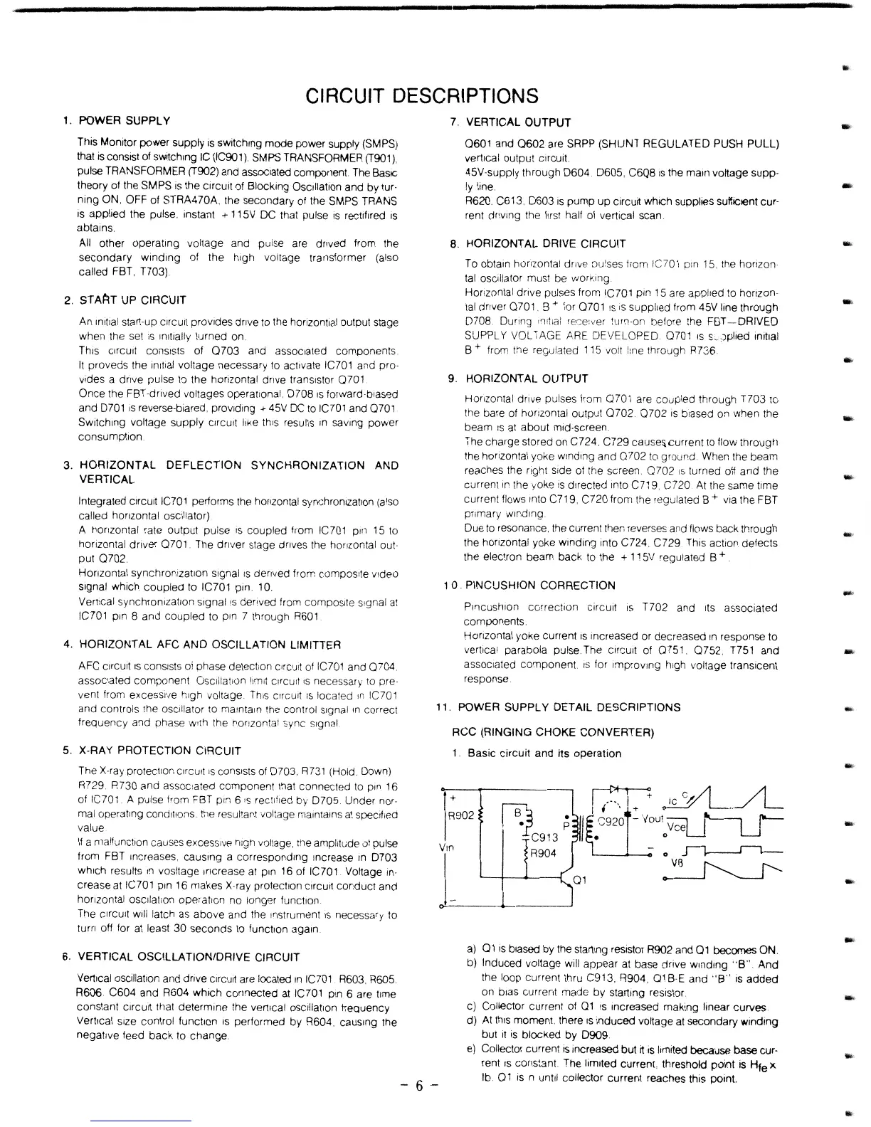
1.
Basic
circuit
and
its
operation
+
r:;-r~~
R902
fB.)
;
I~
~92;1'
V~O<:qJ~
C913
I.
0
R904
-0
~
01
~
-
~-------~--------~
a)
01
IS
biased by the starting resistor R902 and
01
becomes ON.
b)
Induced
voltage will appear
at
base drive
winding
"B"
And
the loop current thru C913. R904.
01BE
and
"B"
IS
added
on bias current
made
by
starting resistor.
c) Collector current of
01
is increased rnaking linear
curves
d)
At
thiS
moment. there
IS
Induced
voltage at secondary Winding
but
It
is
blocked
by
0909.
e) Collector current
is
Increased
but
rt
is
limited because base cur-
rent
IS
cons:ant. The limited current, threshold pOint
IS
Hie
x
lb.
01
is n until collector current reaches this point.
-
..
-
-
-
-
...
 Loading...