Issue 6, 1984 :Computer 33
.. commodore
Model: PLUS 44
©©
1980 COMMODORE BUSINESS MACHINES INC.
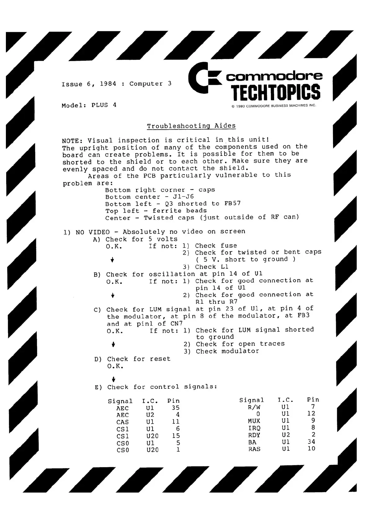
Troubleshooting Aides
NOTE: Visual inspection is critical in this unit!
••
The upright position of many of the components used on the
board can create problems. It is possible for them to be
shorted to the shield or to each other. Make sure they are
evenly spaced and do not contact the shield.
Areas of the PCB particularly vulnerable to this
problem are:
Bottom right corner -caps
Bottom center -Jl-J6
Bottom left -Q3 shorted to FB57
Top left -ferrite beads
Center -Twisted caps (just outside of RF can)
1) NO VIDEO -Absolutely no video on screen
A) Check for 5volts
O.K. If not: 1) Check fuse
2) Check for twisted or bent caps
++ ((
5V. short to ground)
3) Check Ll
B) Check for oscillation at pin 14of Ul
O.K. If not: 1) Check for good connection at
pin 14of Ul
++
2) Check for good connection at
Rl thru R7
C) Check for LUM signal at pin 23of Ul, at pin 4of
the modulator, at pin 8of the modulator, at FB3
and at pinl of CN7
O.K. If not: 1) Check for LUM signal shorted
to ground
++
2) Check for open traces
3) Check modulator
D) Check for reset
O.K.
++
E) Check for control signals:
Signal
I.C.
Pin
Signal
I.C.
Pin
AEC
Ul
35
R/W
Ul
77
AEC
U2
44
00
Ul
12
CAS
Ul
11
MUX
Ul 99
CSI
Ul
66
IRQ
Ul
88
CSl
U20
15
RDY
U2
22
CSO
Ul
55
BA
Ul
34
CSO
U20
11
RAS
Ul
10