ComNav Vector G2 & G2B Installation & Operation Wiring
Using a PC for Vector G2 Control & Display
Figure
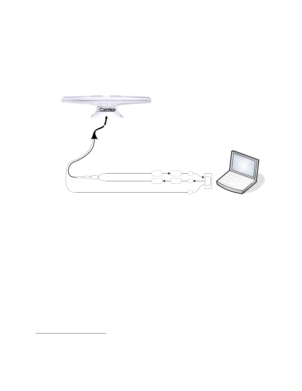
3 shows the typical connections when using a PC, instead of a Navigator G2 Display,
to configure the G2, and/or monitor its status.
Note: the PC is not necessary
4
, if the G2’s factory-default configuration (see page 15)
meets your needs, and if you do not wish to monitor any of the G2’s various status
values.
This wiring scheme uses only the G2’s Port A RS-232 output and input.
GREY
RS-232 Signal Ground
Port A (RS-232)
BLUE
BLACK w/ BLUE STRIPE
PC for Vector G2 Control & Display
(using PocketMAX PC or HyperTerminal)
Tx
Rx
D-Type 9 pin
Female Connector
(user-supplied)
Tx
Rx 2
3
5
PC COM Port
Signal & Pin #
Vector G2 or G2B
Figure 3 – Typical Wiring with a PC for Vector G2 Control & Display
The PC would typically be running a “dumb terminal” program (e.g., the Hyperterminal®
program that comes with Windows® on PCs), or Hemisphere’s own GPS Control & Display
program, PocketMAX PC
5
. More details on using Hyperterminal can be found at various
“Windows Help” sources; see the PocketMAX User Manual for usage instructions on it.
Using a Vector G2 with a PC Navigation Program
Figure
4 shows the typical connections when using a PC, instead of a Chartplotter or some
other type of NMEA Navigation equipment, to perform “Navigation display &/or control”
functions – viewing the vessel’s position on a chart, setting waypoints and so on.
This wiring scheme uses the G2’s Port A RS-232 output (and input, if the PC is also going to
be used to control the G2), and the Port B RS-422 output.
4
… neither is a Navigator G2 Display System, see page 7.
5
This program can be found on Hemisphere’s web site. Note that there is also a PDA version of PocketMAX, which can
be run on a PocketPC. Use of that version, and wiring a PDA to the G2, are not described in this manual.
Document PN 29010078 V1.6 (Addendum #1) - 11 -