The solid state relay, as the name implies, is a solid state switch, controlled
by the C4000. These solid-state switches control the C4000 220-240volt
outputs.
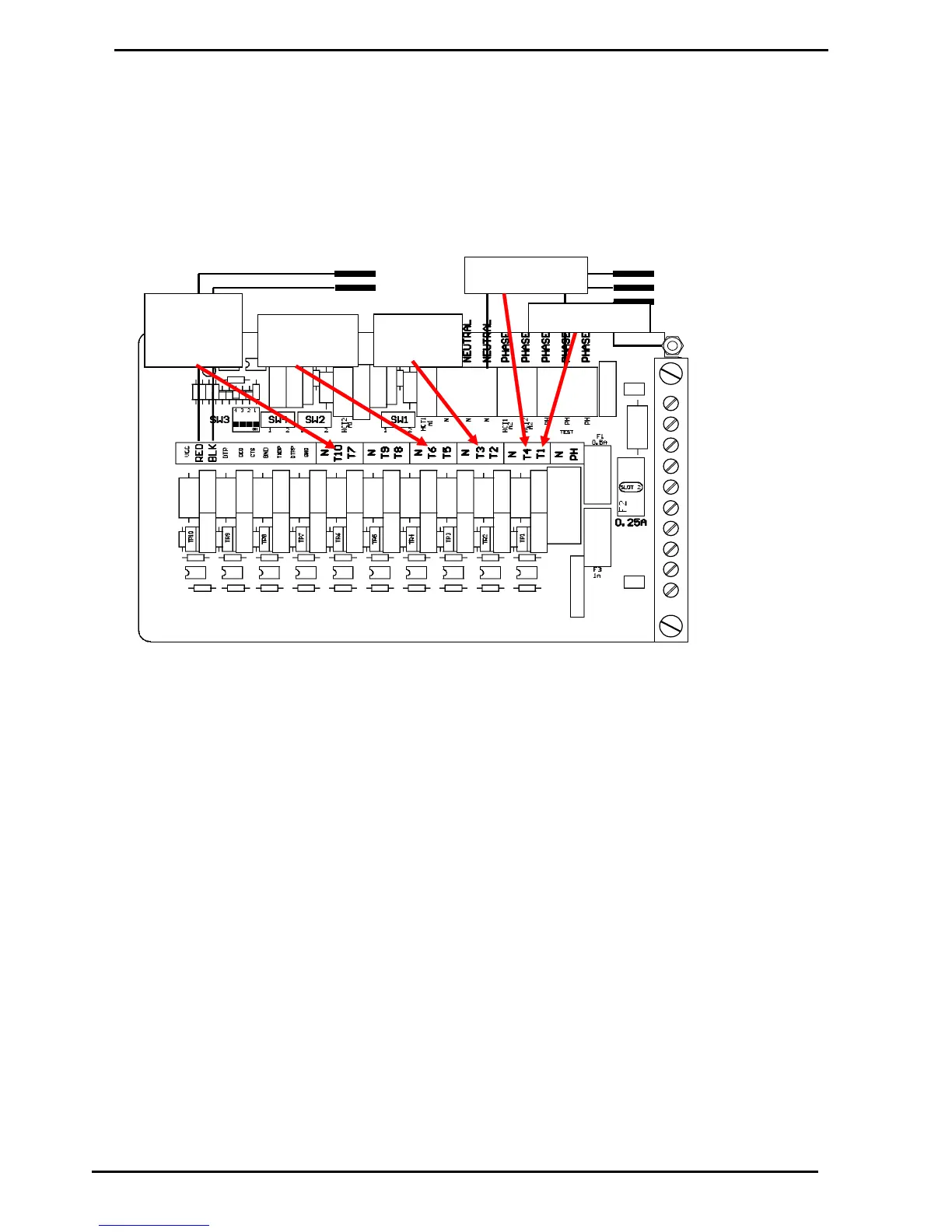
There are 10 separate solid state relays (small triacs) on the C4000 PCB.
The output terminals for these triacs is T1 to T10. Their function varies
depending on what the C4000 'head' is controlling. Below are tables
showing the use of these outputs for various applications.
The T1 and the T4 outputs can be used to drive a high current triac whose
output will be on the LOAD1 and LOAD2 terminals respectively. Each of
these outputs (T1 and T4) has an associated switch (SW1 and SW2
respectively) which must be used to select the type of output required (refer
Figure 8).
The T7 output cannot drive a high current triac directly but may be looped to
T1 or T4 of another C4000. If it is looped then SW4 must be in the mid
position. Position 1 of SW4 should never need to be used.
The power for the triac outputs can be supplied from a separate mains
supply (Separate from the supply for the microprocessor). There are two
blocks of connectors for the phase connection (refer Figure 7). The block of
six connectors supplies the microprocessor and the block of four connectors
supplies the triac outputs. These two blocks of connectors are normally
looped together in the factory.