Basic Systems (Comcard Compin & CWIDKey)
Power for the C4000 'head' connects to the terminals marked Phase,
Neutral, & the Earth Stud.
Refer Connecting Mains Power and Communications (see page 10)
On the C4000 Power supply PCB, the incoming phase feeds the
microprocessor power supply through the fuse F2 (250mA) and feeds all
low current solid state relay circuits through the fuse F3 (1A).
Solenoids and motors are connected to the appropriate terminals.
Communications (Comms)
Wiring
Communication cables connect to the comms terminals marked Red and
Black.
Refer Connecting Mains Power and Communications (see page 10)
The Communications wiring is a 12 volt circuit and any
contact with mains will cause permanent damage.
The C4000 can communicate with the following Forecourt Controllers:
Micro M
Eftpec
Compac Central Controller
Task
Postec
Compac Commander
Comms DIP Switch settings
The Comms dipswitches are on the C4000 power supply PCB. Refer
Figure 7 Solid State Relays (Triacs) (see page 61)
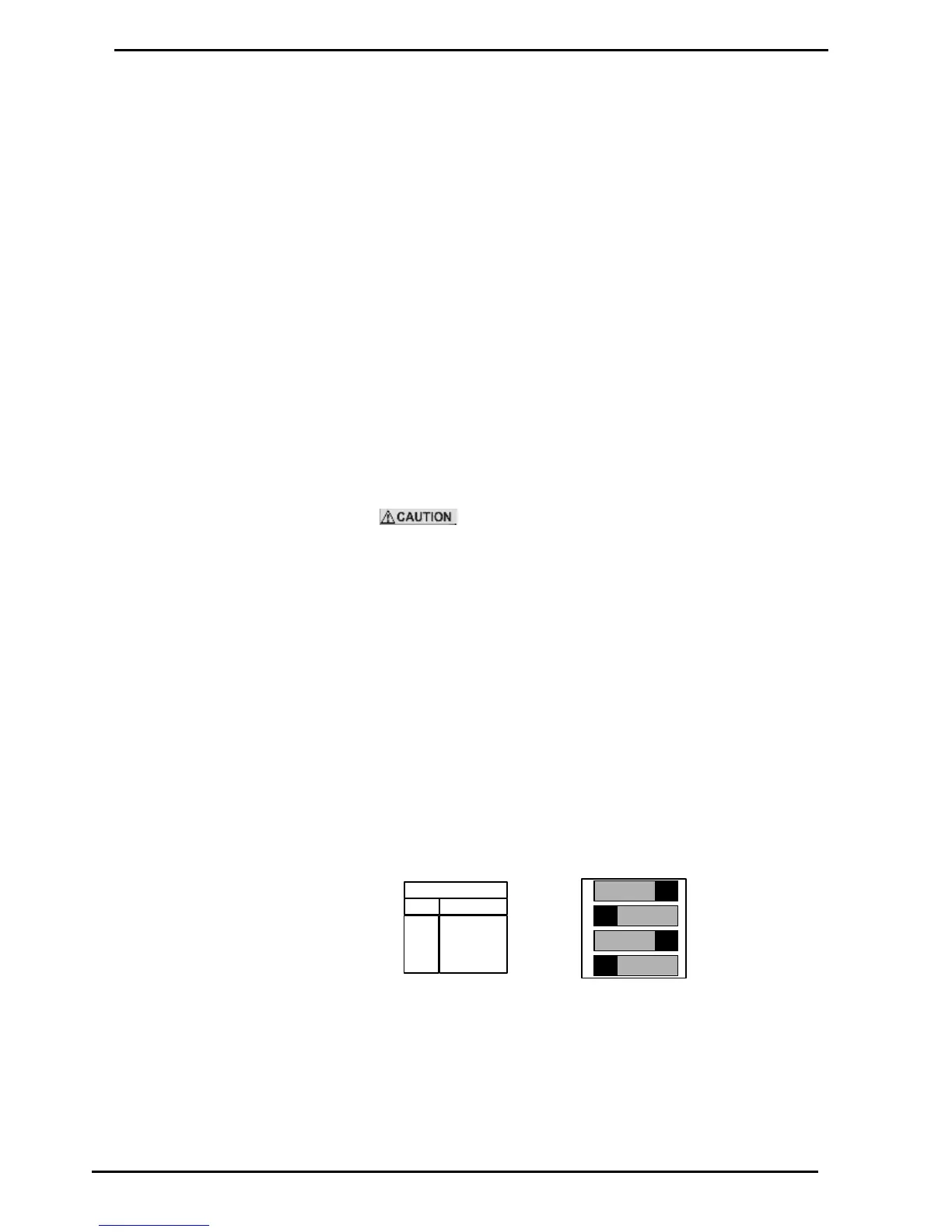
Figure 9. Comms DIP Switch Settings
Standard Compac Comms (or PEC Comms)
Switch 1,3 ON
Switch 2,4 OFF
With Gilbarco consul interface
Switch 1,3 OFF