78
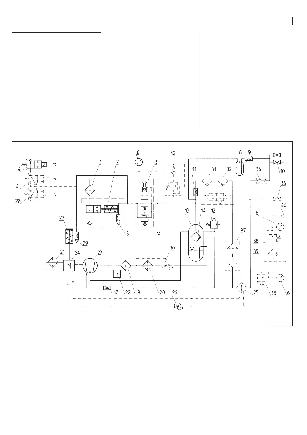
Fig. 4
135 028 74
4. Construction and functional description
4.3
System description
1. Air filter
2. Intake control valve
3. Control unit (proportional controller +
start-up without load)
4. Release valve
5. Nozzle controller
6. Pressure gauge
8. Oiler reservoir
9. Oiler valve
10. Taps
11. Venturi nozzle
12. Safety valve
13. Pressure tank
14. Fine separator
17. Orifice, evacuation line
19. Oil filter
20. Oil cooler compressor
21. Oil cooler engine
22. Temperature switch
23. Compressor
24. Diesel engine
27. Engine actuating cylinder
29. Nozzle
Generator option
28. Solenoid valve
Generator with pressure reduction
option
28. Solenoid valve
41. Solenoid valve
42. Pressure retaining non-return valve
Option Heat exchanger
25. Heat exchanger
26. Oil temperature control
Option oil temperature control
30. Oil temperature control
Option After cooler
31. Cooler
32. Condensate separator
25. Heat exchanger
26. Oil temperature control
35. Backlash valve
36. Extraction lever oil-free compressed air
Option filter
37. Filter combination
Option clean air
38. Pressure control
39. Activated carbon filter
40. One-hand coupling