79
Fig. 5
135 033 74
4. Construction and functional description
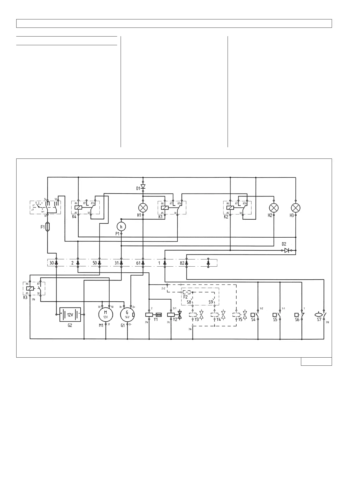
4.4 Wiring diagram
S1 Main switch
S2 Start switch
S3 Signal interrupt switch
S4 Engine temperature switch
S5 Compressor temperature switch
S6 Engine oil pressure switch
S7 Fuel shortage
Optional:
S8 Generator automatic idling control
(optional)
S9 Generator pressure reduction (optional)
Y1 Solenoid actuator
Y2 Solenoid valve for pressure relief
Optional:
Y3 Solenoid valve generator automatic
idling control (optional)
Y4 Solenoid valve generator pressure
reduction (optional)
Y5 Solenoid valve aftercooler condensation
drainage (optional)
D1 Diode
Optional:
D2 Fuel shortage shut down
H1 Battery charge pilot lamp
H2 Fault pilot lamp
H3 Fuel shortage
K1 Relay - fault
K2 Relay - fuel shortage
K3 Relay – start-up
K4 Relay – start lock
G1 Three-phase generator
G2 Battery
M1 Starter
P1 Hours of operation counter
F1 Fuse 5 A
F2 Fuse 5 A (generator)