page 21
V100-VL400 User Manual – Installation
The only connections required to the compressor
are as follows:
1. Air delivery outlet to the aftercooler/receiver.
2. Electrical power supply to drive motor:
3-phase plus earth.
3. Electrical connections to the safety switch.
4. Air pipe from the air governor to the receiver.
5. Cooling water pipes (water cooled intercooler/
aftercooler models only).
6. Condensate drain to the users disposal
system.
The compressor should be installed in a cool and
clean location and positioned to allow the necessary
access and headroom for the removal of
components. A minimum of 1 m all round and clear
headroom of 1.5 m is recommended. Walkways,
passages and doorways must not be obstructed.
If the air intake filter is to be installed in a position
remote from the compressor an adaptor for the
intake manifold will be required. Consult the local
CompAir distributor for advice regarding the
dimensions of the extension pipe. If the air intake
filter is to be positioned on the outside of the
building it must be protected from the weather.
An air receiver of appropriate size should be
installed with a manually operated valve between the
compressor and the air receiver. A safety pressure
relief valve must also be fitted between the
compressor delivery outlet and the isolating valve.
Providing the compressor is arranged for normal
speed running, any air pipework between the
compressor delivery flange and the air receiver must
on no account be smaller than the delivery flange.
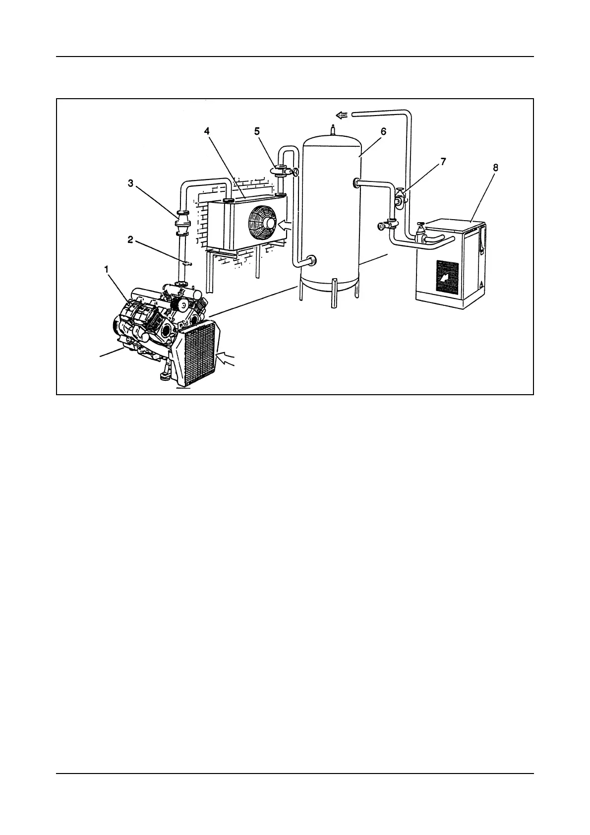
1. Compressor
2. Safety Relief Valve
3. Non-Return Valve
4. Air-Blast Aftercooler
5. Isolating Valve
6. Receiver
7. By-Pass Valve
8. Refrigerant Dryer
TYPICAL INSTALLATION/GENERAL ARRANGEMENT