page 23
V100-VL400 User Manual – Installation
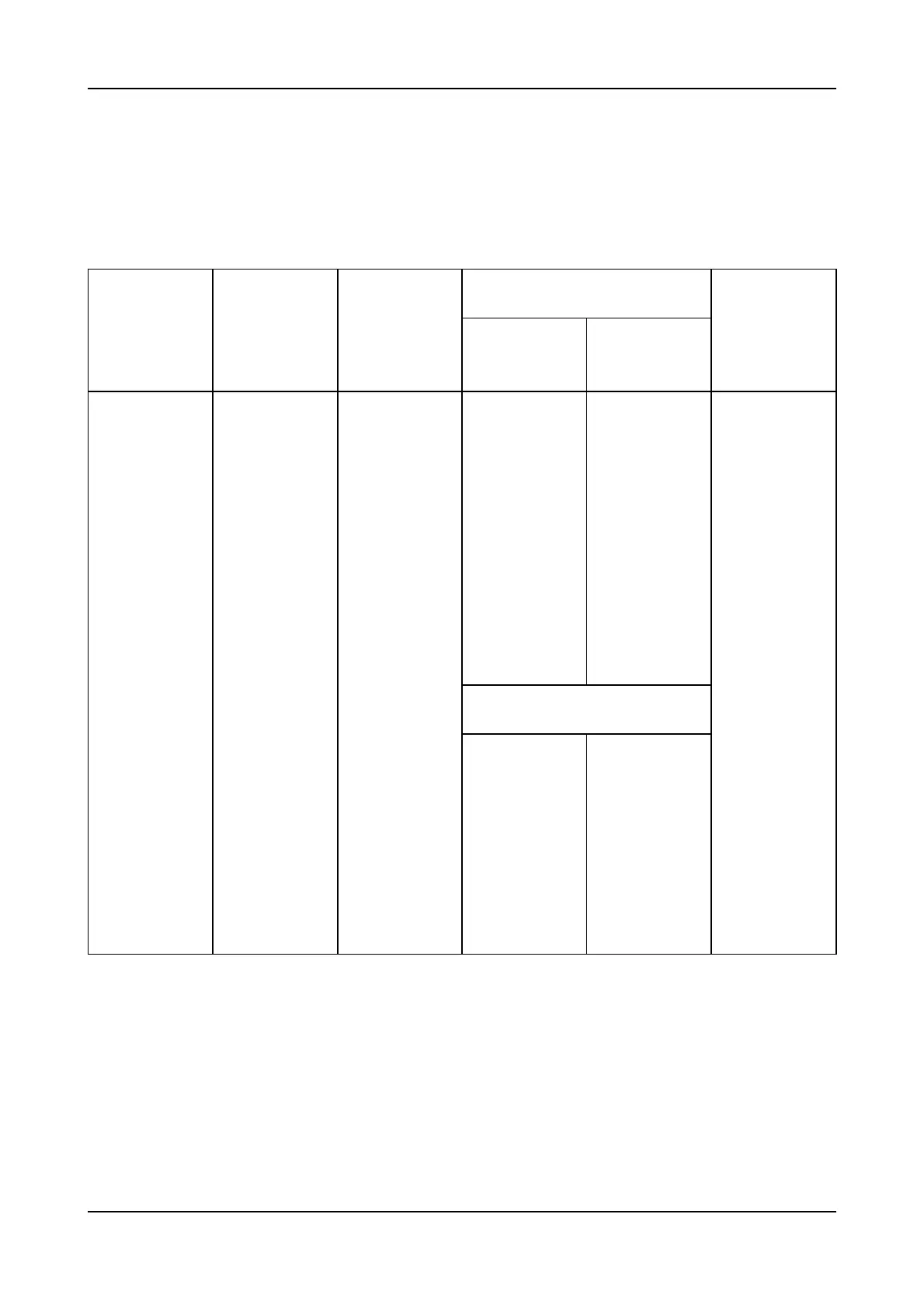
Room volume Additional area
Model Room volume with aftercooler to inlet opening
7 bar 10.5 bar for aftercooler
m
3
m
3
m
2
m
2
m
2
V100A 29 43 0.45 0.55 0.25
V100W 29 - 0.45 0.55 -
V100DA 29 43 0.45 0.55 0.25
V100DW 29 - 0.45 0.55 -
V150A 43 64 0.7 0.8 0.4
V150W 43 - 0.7 0.8 -
V150DA 43 64 0.7 0.8 0.4
V150DW 43 - 0.7 0.8 -
V200A 57 85 0.9 1.05 0.5
V200W 57 - 0.9 1.05 -
V200DA 57 85 0.9 1.05 0.5
V200DW 57 - 0.9 1.05 -
VL200A 29 57 0.4
VL200DA 29 57 0.4
V300A 85 128 1.3 1.5 0.8
V300W 85 - 1.3 1.5 -
V300DA 85 128 1.3 1.5 0.8
V300DW 85 - 1.3 1.5 -
VL300A 43 85 - - -
VL300DA 43 85 - - -
VL400A 57 114 - - -
VL400DA 57 114 - - -
Total area of ventilation
inlet and outlet openings
0.4 (up to 2.5 bar only)
0.4 (up to 2.5 bar only)
3. VENTILATION
In operation the compressor will release heat into the surroundings and therefore the compressor room should
be of adequate size and have good ventilation. The recommended minimum sizes of room and ventilation
openings are as below:
If any difficulties are anticipated or if there are space limitations on site consult the local CompAir distributor
before installation is commenced.