CompAir Limited
page 44
APPENDIX 1
THE PRESSURE SYSTEMS SAFETY
REGULATIONS 2000
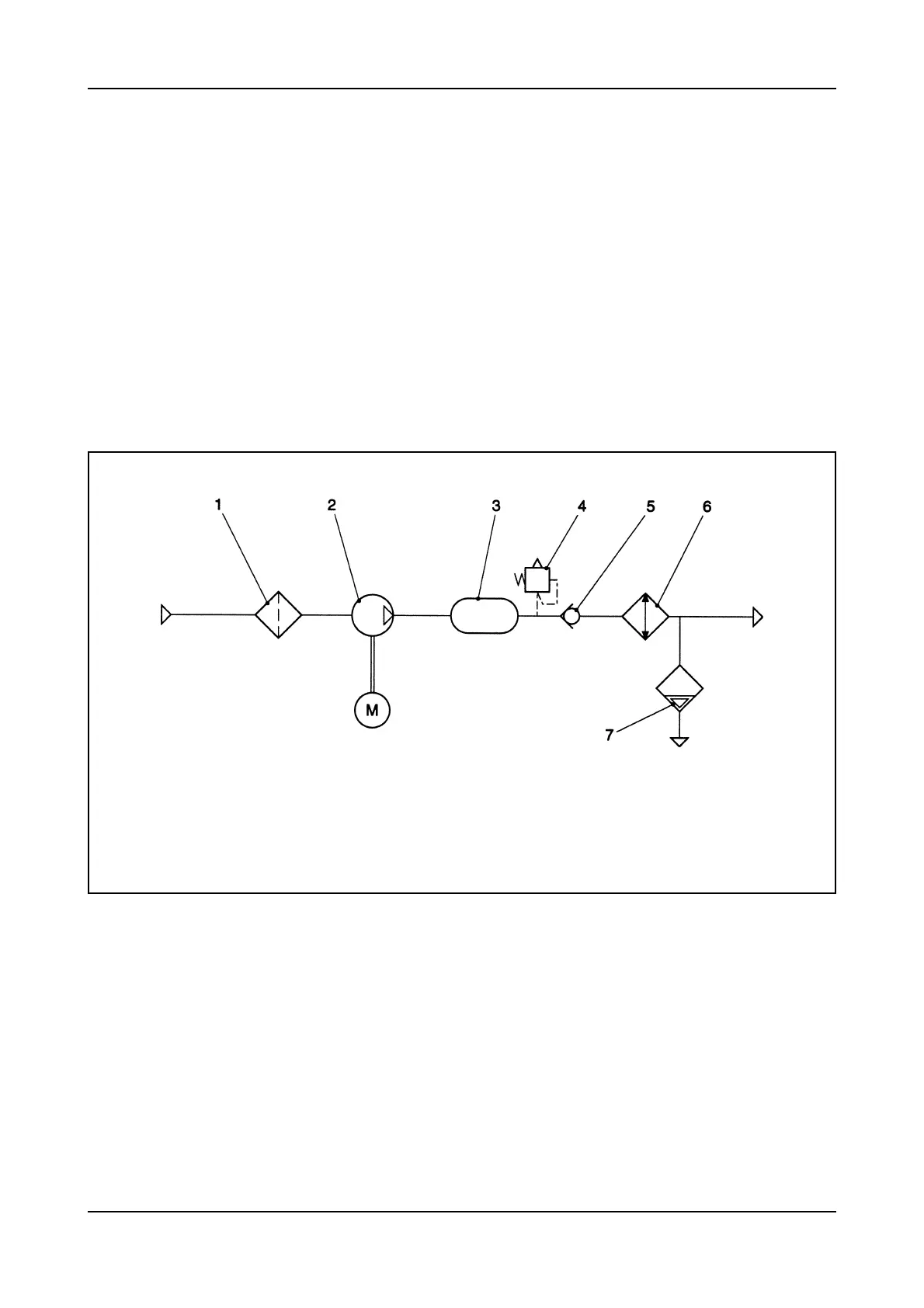
The circuit diagram shown below is provided to
assist a 'competent person' in preparing a written
scheme of examination for a system incorporating
the air compressor(s).
Note: The intervals between examination and
calibration of components, eg pressure vessels,
pressure relief valves etc, will be defined by the
'competent person' preparing the written scheme.
In defining these periods the 'competent person'
must take into account the recommendations of the
component part manufacturer, the Health and Safety
Executive (H & SE) and the British Compressed Air
Society (BCAS).
1. Intake Air Filter
2. Compression Cylinder
3. Pulsation Vessel
4. Pressure Relief Valve
5. Non-return Valve
6. Aftercooler
7. Auto Drain Trap
PRESSURE SYSTEM DIAGRAM – 1ST STAGE