— 5 —
P900
1
2
A board
D board
rotate 180º
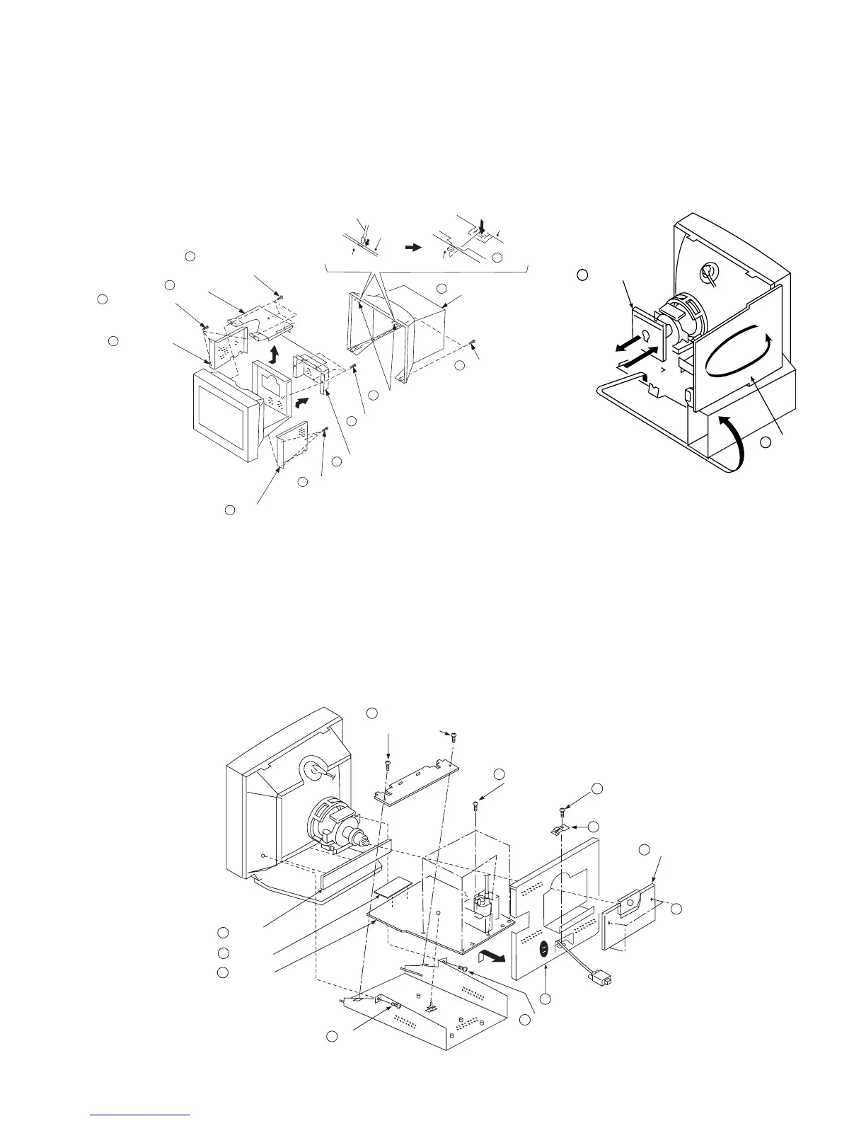
1-3. D, A, H and N BOARD REMOVAL
1-1. CABINET/SHIELD REMOVAL
1-2. SERVICE POSITION
SECTION 1
DISASSEMBLY
1 When the D board is placed in service position, the Safety Earth Wire
(black wire) is disconnected.
2 After service is completed and the D board reinstalled, the Safety Earth
Wire must be reattached to the chassis. This must be confirmed before
any subsequent procedures are attempted.
To remove the rear cover of the unit, press in and unsnap the claw on
the right side of the unit, then press in and unsnap the right claw at the
top of the unit. Repeat this with the claw on the left side and top left
of the unit and remove.
Video shield
Two claws
Three screws
(+BVTT 4 x 8)
Two screws
(+ BVTP 4 x 16)
1
2
6
7
5
4
3
2
Two claws
Four screws
(+ BVTP 4 x 8)
Top cover
Bezel assembly
Bezel assembly
Cabinet
Cabinet
Push in the tip of a screwdriver
about 5mm to unlock the claw.
Cabinet
Three screws
(+BVTT 4 x 8)
8
Three screws
(+BVTT 4 x 8)
8
9
Side cover
9
Side cover
Cable bracket
D board
Five screws
(BVTP 3 x 8)
2
6
4
8
Holder
5
A board
N board
10
H board
11
One screw
(BVTT 4 x 8)
3
Three screws
(BVTT 4 x 8)
1
Two screws
(BVTT 4 x 8)
9
One screw
(BVTT 4 x 8)
7
One screw
(BVTT 4 x 8)
7