— 6 —
P900
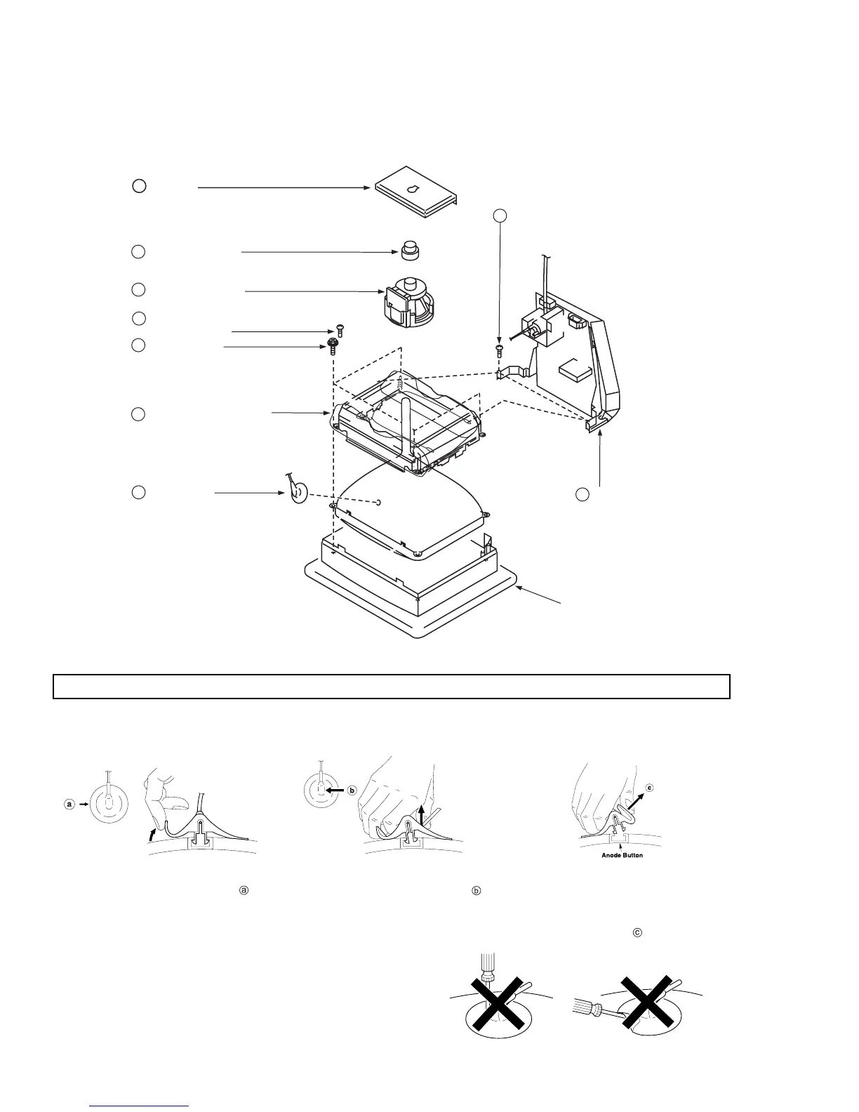
1-4. PICTURE TUBE REMOVAL
HOW TO HANDLE AN ANODE-CAP
1. Do not use sharp objects which may cause damage to the surface
of the anode-cap.
2. Do not squeeze the rubber covering too hard to avoid damaging the
anode-cap. A material fitting called a shatter-hook terminal is built into
the rubber.
3. Do not force turn the foot of the rubber cover. This may cause the
shatter-hook terminal to protrude and damage the rubber.
REMOVAL OF THE ANODE-CAP
WARNING: Short circuit the anode of the picture tube and the anode-cap to the metal chassis, CRT shield or carbon painted on the
CRT, after removing the anode.
REMOVAL PROCEDURES
A board
2
Neck assembly
3
Deflection yoke
4
Four screws
(Tapping screw 5)
6
Anode-cap
1
Stand
assembly
(D board)
8
Two screws
(BVTP 4 x 16)
7
Cushion
Tension spring
Demagnetization coil
Picture tube shield
9
Two screws
(BVTP 4 x 16)
5
2. Use your thumb to pull the rubber cap firmly
in the direction indicated by arrow .
1. Turn up one side of the rubber cap in
the direction indicated by arrow .
3. When one side of the rubber cap
separates from the anode button, the
anode-cap can be removed by turning
the rubber cap and pulling it in the
direction of arrow .