5–70 Maintenance and Service Guide
Removal and Replacement Procedures
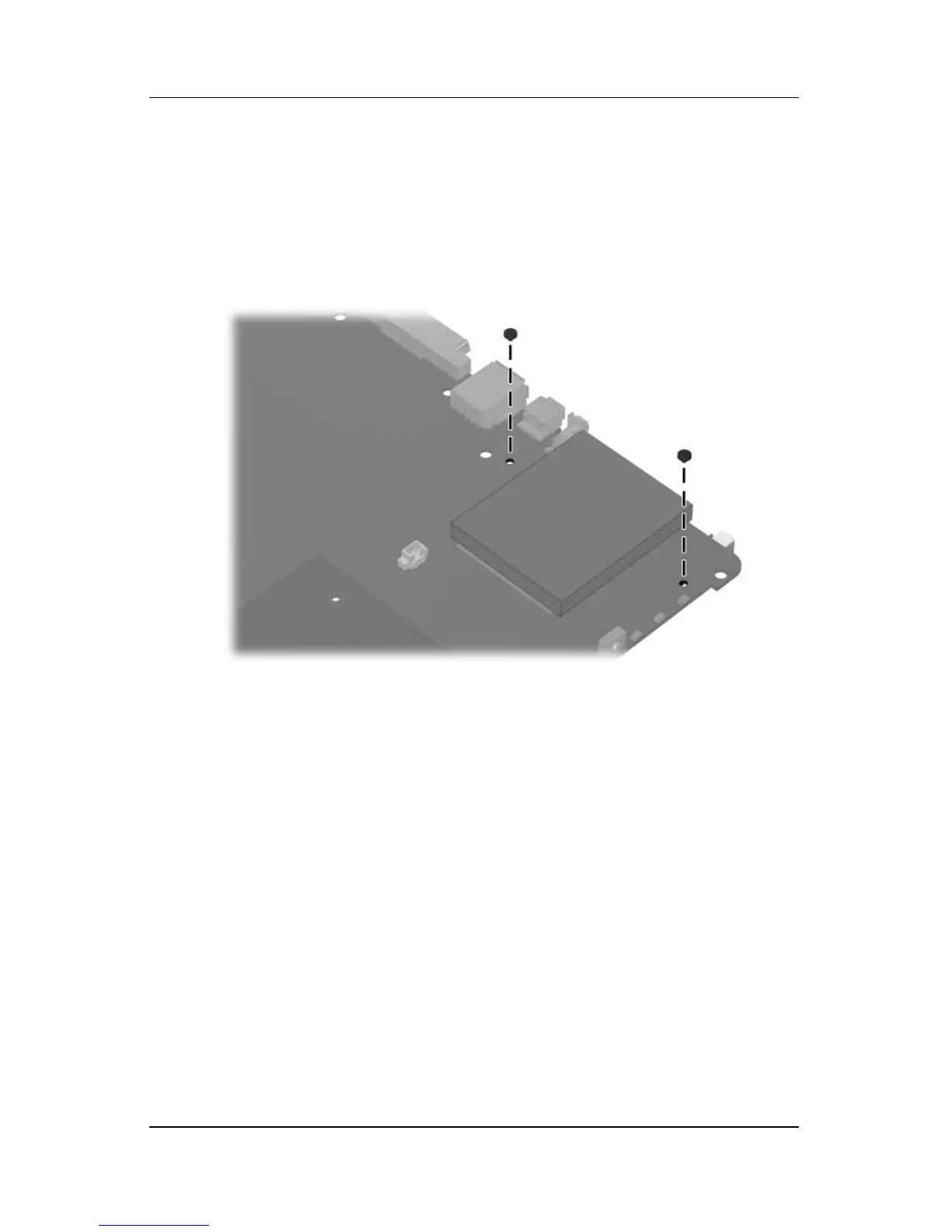
2. Turn the system board upside down with the expansion port 2
toward you.
3. Remove the two PM2.0×4.0 screws that secure the PC Card
assembly to the system board.
Removing the PC Card Assembly Screws