Compu Pool CPSC Series Manual 12
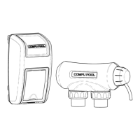
7.4 Installing the Power Unit
7.4.1 Mount the Power Unit as close to the pump and filtration system as possible. Make
sure the 6’ DC cell power cord can reach the section of pipe selected for the cell.
Do not install the Power Unit within 10 feet of the pool edges.
7.4.2 Using the provided screws and anchors, secure the mounting bracket at eye level.
Once the mounting bracket is tightly secured, lift the Power Unit onto the mounting
bracket and secure with the provided screws.
7.4.3 A lug for bonding is attached to the bottom of the Power Unit (see Figure 4).
Connect to the pool bonding system using minimum 8 AWG copper wire if required
by code.
7.5 Installing the Electrolytic Cell (Recommended Horizontal
Installation)
7.5.1 Be sure the pool pump is turned off.
7.5.2 The cell is to be fitted into the return line to the pool after the pump, filter and heater
(if applicable). Water flow should come from the filtration system through the
socket marked “inlet” and back out through the hole marked “outlet”.
7.5.3 Make sure that the 6 foot cell power cord reaches from the power unit to the area
where you will be installing the cell. Compu Pool also has units available that come
with 15 foot cell cords (must be requested at time of purchase).
7.5.4 Taking into consideration your existing plumbing, measure and cut the pipe before
the last entry to the pool accordingly.
7.5.5 Install 90 degree elbows and vertical pipe to meet both the inlet and outlet barrel
unions.
7.5.6 Position the cell on the vertical pipes (use pressure solvent cement to glue the
piping to the barrel unions), making sure that the inlet and outlet are positioned
correctly and that the cell is level.
7.5.7 Ensure the barrel union collar nuts are secured tightly to the cell housing.
7.5.8 Remove the Blue UV covers.
7.5.9 Connect the three cell lead connectors to the cell terminal posts as follows:
Connect the red lead to the top terminal post
Connect the blue lead to the middle terminal post
Connect the black lead to the bottom terminal post
7.5.10 Slide the clear connector cap up the cell cord and position against the cell head.
7.5.11 Slide the collar nut over the clear connector cap and tighten.