12
COMUNELLO ®Copyright 2013 - All right reserved
4 INSTALLATION
4.1 PRELIMINARY CHECKS
Before starting the installation work, check the condition of the product
components, the suitability of the chosen gate opener model and the
suitabilityoftheintendedinstallationenvironment:
• Ensurethatallmaterialusedisinperfectconditionandtforpurpose.
• Makesure that the mechanical structure of the gate is suitable for
automation. This product cannot be used to automate a gate unless
the gate is already in good working order and safe; furthermore, it
cannot remedy defects caused by incorrect installation or lack of
maintenanceofthegate.
• Checkthattheoperatingconditionsofthedevicesarecompatiblewith
the stated operating limits.
• Movethegateleavesmanuallyinbothdirectionstoensuretheforce
requiredisconstantthroughoutthefullrangeofmovement.
• Movethe gate leavesmanually to anyposition then release them to
checkthattheyremainstationary.
• Checkthattheareainwhichtheoperatoristobemountediscompatible
withthesizeoftheunitandmakesurethereissufcientclearancefor
thefullmovementofthearm.
• Ensurethatthereissufcientspacearoundtheoperatortoperformthe
manual release procedure.
• Ensurethatthesurfacesonwhichthedevicesaretobemountedare
solid and able to provide a secure anchorage.
• Ensurethatalldevicestobeinstalledareinaprotectedlocationsuch
thatminimizestheriskofaccidentalimpact.
4.2 OPERATING LIMITS
Beforestartingtheinstallationworkmakesuretheoperatoriscorrectlysized
inrelationtothedimensionsandlengthofthegateleavesandwithinthe
limitsofthevaluesgiveninthechapter“Producttechnicalspecications”.
4.3 PREPARATORY WORK FOR INSTALLATION
WithreferencetoFIG.1AeaFIG.1B,choosetheapproximateposition
inwhicheachcomponentofthesystemistobeinstalledandchoosethe
mostappropriateconnectionlayout.Listofcomponentsrequired:
• Electromechanicaloperators.
• Pairofphotocells.
• Pairofopeninglimitstopsandclosingstop.
• Postsforphotocells.
• Flashinglight.
• Keyselectorswitchordigitalkeypad.
• Verticalelectriclock(recommendedforgateleavesofmorethan3m).
• Controlunit.
4.4 INSTALLING THE RAM OPERATOR
4.4.1 INSTALLATION
Performthemanualreleaseasdescribedinheading4.4.3
• Choose the position for the gate opener in correspondence with a
sturdy cross member on the gate.
• Temporarilysecuretherearplatetothepillar,whichmustbeatleast100
mminwidth(FIG.2).
• Withthegatefullyclosed,xthefrontplatetothegateleaf(FIG.3).
• Coupletheoperatortotherearbracketusingthesuppliednutandbolt
(FIG.4).Theoperatorcannotbeinstalledwiththecoverupward.
• Fixtherodtothefrontplatewiththesuppliednutandbolt(FIG.4).
4.4.2INSTALLATIONOFLIMITSTOPSANDSWITCHES
TheRAMoperatorisnotequippedwithelectroniclimitswitchesanditis
thereforeessentialtoensurethatthegatetobeautomatedisequippedwith
mechanical opening and closing limit stops.
4.4.3OPERATORMANUALRELEASE
Perform the manual release procedure when the gate is to be opened
manually. Activation of the release system may result in uncontrolled
movementsofthegateinthepresenceofimbalanceormechanicalfaults.
Toreleasetheoperator,proceedasfollows:
• Opentheplastichatchandinsertthereleasehandle(FIG.5).
• Turnthehandleclockwise(FIG.6).
• Thisactionservestodisengagethegeartherebyallowingthegatetobe
openedmanually(FIG.7).
• To resume automatic control of the gate, return the key to its initial
position(FIG.8)
• Removethereleasehandleandstowitinasafeplace(FIG.9).
5 PREPARATION FOR ELECTRICAL
CONNECTIONS
• Performthemanualreleaseasillustratedinheading4.4.3.
• RemovetheplasticcoverasshowninFIG.10.
• Loosencablegland“G”locatedonthelowersideoftheoperatorFIG.10.
• InsertthepowercableFIG.11.
• Connectthewirestotheterminalboardasshownontheadjacentlabel.
• Connecttheearthwiretotheterminaleyenexttotheterminalboard
FIG. 11.
• Securethecablebytighteningthecablegland.
6 TESTING
Each part of the automation system, e.g. safety edges, photocells,
emergency stop, etc. must be tested; follow the procedures shown in
theinstructionmanualssuppliedwiththedevicesinquestion.Performthe
followingsequenceofoperationsfortestingofRAM:
• Checkthatalltheprescriptionsinthismanualhavebeenfollowedscrupulously,
withspecialattentiontothematterssetdowninchapter1“Prescriptions”.
• Using the supplied control or stopping devices (key selector switch,
controlbuttonsorradiotrasmitters),performgateopening,closingand
stoppingtestsandmakesurethegaterespondscorrectlytothevarious
commands.
• Checkoperationofallthesystem’ssafetydevices(photocells,safety
edges,emergencystop,etc.)onebyone.
• Ifpotentiallyhazardoussituationscausedbymovementofthegateleaf
havebeeneliminatedbylimitationofimpactforce,theassociatedforce
must be measured as prescribed in standard EN 12445.
7 PRODUCT MAINTENANCE
Maintenancemustbecarriedoutatregularintervalsbyqualiedpersonnel
incompliancewiththeprovisionsofstatutorylegislationandtheregulations
in force. RAM must be serviced at least once every 6 months or after
10.000 operating cycles since the last service.
• Disconnecttheoperatorfromallpowersupplies
• Checkallthemovingpartsandreplaceanywornparts.
• Checkallpartsoftheautomationsystemforsignsofdeterioration.
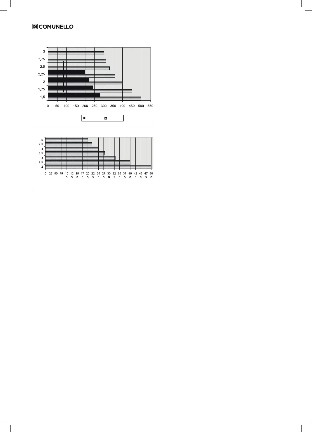
RAM 300RAM 220
LEAF WEIGHT (Kg)
LEAF LENGHT (m)
LIMITS OF USE - RAM 220 - RAM 300
LEAF WEIGHT (Kg)
LEAF LENGHT (m)
LIMITS OF USE - RAM 500
 Loading...