EasyManua.ls Logo

Confer Plastics STEP-1 - User Manual

Confer Plastics STEP-1
4 pages
Print Icon
To Next Page IconTo Next Page
Loading...
SAND
Note: 40 lbs.
of sand
required!
(See Step 8)
SAVE THESE INSTRUCTIONS
DEALER/INSTALLER: GIVE TO HOMEOWNER
CONFER-STEP-1
Above-Ground Pool Steps
ASSEMBLY AND INSTALLATION MANUAL
Made in the U.S.A. by
www.conferladders.com
Question and Answer IconNeed help?

Do you have a question about the Confer Plastics STEP-1 and is the answer not in the manual?

Summary

Assembly and Installation Steps

Step 1: Prepare Handrail Posts

Remove locking wedges and separate handrail posts by cutting them apart.

Step 2: Attach Steps to First Side Panel

Lay a side panel flat and push steps into openings, ensuring riser grooves align.

Step 3: Insert Risers

Place risers between steps, aligning ends in the panel's riser recesses.

Step 4: Attach Second Side Panel

Position and press the second side panel onto steps and risers until fully seated.

Step 5: Secure Steps with Wedges

Insert locking wedges between side panels and steps to secure them.

Step 6: Attach Bases

Secure bases to side panels using four screws per panel.

Step 7: Position and Lubricate Posts

Place unit near pool, lubricate plain ends of handrail posts for insertion.

Step 8: Add Sand for Stability

Pour approximately 10 lbs. of dry sand into each of the four openings.

Step 8 a: Attach Long Handrail Posts

Fasten long handrail posts to side panels with screws, ensuring correct orientation.

Step 9: Attach Mounting Brackets

Slide mounting brackets onto higher handrail posts and affix 'No diving' labels.

Step 10: Attach Short Handrail Posts

Insert short posts into lower holes of the side panel up to the indicated line.

Step 11: Attach Handrails

Lubricate handrail ends and insert into posts until seated, securing with screws.

Step 12: Secure Unit to Deck

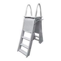
Position unit in pool, attach brackets to deck, and secure brackets to handrail posts.

Safety Information and Recommendations

General Safety Precautions

Follow manufacturer's recommendations for tools, intended use, and lifting.

Weight Restriction Warning

Maximum step weight is 400 lbs; exceeding may cause unit failure.

Building Department Consultation

Consult local building department before pool and equipment installation.

Pool Winterization and Storage

Removing Unit for Winter

Suggests removing unit for off-season; provides methods for removal and draining.

Storage Recommendations

Unit can be covered and stored outdoors after water is drained.

Product Warranty Information

Limited Pro-Rated Warranty

Warrants against defects for one year; provides pro-rated costs for subsequent years.

Return Policy for Defects

Defective parts must be returned postpaid with proof of purchase.

Overview

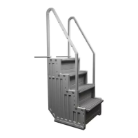
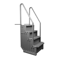
The Confer-Step-1 is an above-ground pool step system designed for safe and easy entry and exit from flat-bottom above-ground pools. It is manufactured in the U.S.A. by Confer Plastics Inc. and comes with an assembly and installation manual for dealers and homeowners.

Function Description:

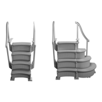
The primary function of the Confer-Step-1 is to provide a stable and secure means of access into and out of an above-ground swimming pool. It is designed to be placed inside the pool, offering a series of steps for users. The system includes handrails for added support and stability during use. A crucial safety feature is the requirement to fill the steps with sand to prevent floating, ensuring the unit remains submerged and stable. The steps are designed for flat-bottom pools only and are not suitable for dished or sloped bottoms.

Important Technical Specifications:

  • Weight Capacity: The maximum weight on the steps should not exceed 400 lbs. Exceeding this limit may cause the unit to fail.
  • Sand Requirement: Approximately 40 lbs of dry sand are required to fill the four openings within the steps to prevent floating. This sand needs to be distributed evenly, and adding water can assist in this process.
  • Materials: The steps are made of durable plastic components.
  • Dimensions (implied by parts list): The system consists of two bases, two side panels, two handrails, two long handrail posts, two short handrail posts, four risers, and four steps. The handrail posts come in two lengths: 36-1/4" and 43-1/2".
  • Hardware: The assembly requires 22 #10 x 1-1/4" screws, two "No Jumping/Diving" labels, and two mounting brackets.
  • Tools Required for Assembly: Mallet or hammer and block of wood, Phillips screwdriver, cordless drill motor, 1/8" drill bit, knife, pliers, liquid soap or spray lubricant, and sand (approximately 40 lbs.).

Usage Features:

  • Assembly Process: The assembly involves several steps:
    1. Step 1: Remove and save locking wedges from step ends. Separate the four handrail posts into two long and two short posts.
    2. Step 2: Lay one side panel flat, ensuring the "wording is facing forward." Push step ends into openings, aligning riser grooves and ensuring "Danger No Jumping/No Diving" markings face forward.
    3. Step 3: Insert risers between steps, aligning ends in riser recesses on the panel. Position risers so the center hole faces the "back" of the steps.
    4. Step 4: Position the second side panel over the steps and risers, pressing it down until all components are fully seated. A mallet or hammer and block of wood may be needed to fully seat it.
    5. Step 5: Secure each step by fully inserting the saved locking wedges between the side panel and the top surface of both ends of each step.
    6. Step 6: Position the base under the side panel and secure it with four #10 x 1-1/4" screws, using the molded locators on each tab.
    7. Step 7: Place the assembled unit on the deck. Prepare handrail posts by coating the "plain ends" with liquid soap or spray lubricant. The "top end" is H-shaped to accept handrails.
    8. Step 8 (Crucial for Stability): Pour approximately 10 lbs of dry sand into each of the four indicated openings to prevent floating. Shake the unit to distribute sand evenly; water can help.
    9. Step 8a: Fasten the long handrail posts to the side panels with one #10 x 1-1/4" screw per post, approximately 1 inch below the hole mouth. Insert long handrail posts into the upper holes, ensuring "top" ends point up. Insert short posts into the lower holes of the side panel to the indicated line.
    10. Step 9: Spray mounting brackets with lubricant and slide them over the two higher handrail posts, extending away from the steps. Affix "No jumping - No diving" stickers to the upper end of one handrail post (one facing the pool, one facing away). Note: Mounting brackets are not attached if using an enclosure kit or SIG system.
    11. Step 10 (Requires Two People): Carefully place the assembled unit into the pool and tip it 45° left, right, and forward to fill the steps with water. Repeat if the steps continue to float.
    12. Step 11: Spray handrail ends with lubricant and slip them into the open ends of the posts until fully seated. Secure in place using one #10 x 1-1/4" screw per post.
    13. Step 12: Position the unit between upright posts of the pool, close to the pool top seat. Slide mounting brackets down to the deck surface. Fasten to the deck with two 1/8" pilot holes using the preformed holes in the brackets, securing with two #10 x 1-1/4" screws per bracket. If the bracket is too short, extend the deck surface. Secure brackets to handrail posts with one #10 x 1-1/4" screw per bracket.
  • Safety Labels: "No Jumping/No Diving" labels must be affixed to the handrail posts as indicated.
  • Compatibility: Designed for flat-bottom above-ground pools only. Not for dished/sloped bottoms.
  • Optional Enclosure Kit: The Confer-Step-1 can be integrated with an optional #Step-Enc Enclosure Kit and an additional #Step-1 to create an "up-and-over step system with gate." Specific instructions are provided for this configuration, including not attaching mounting brackets or handrails as described in the standard assembly.

Maintenance Features:

  • Winterization: It is suggested to remove the Confer-Step from the pool for off-season months.
    • If attached to a deck: Two people are required. Disconnect mounting brackets. The person in the water lifts the unit while the person on the deck pulls and guides it out. Once on the deck, allow water to drain from the steps, then lay the unit on its back to drain water from side panels.
    • If getting into the water is not an option: Two people standing on the deck can lift and tilt the unit to drain some water. Once light enough (at least 130 lbs), carefully lift it from the pool.
    • With Enclosure/Connector System: Disconnect the two units by removing the center platform/side rail assembly. Do not stand on the top step of the outside unit as it may tip. Lift the unit inside the pool and tilt it to drain water. Once light enough, carefully lift it over the side of the pool, lay it on its back, and allow most water to drain from the side panels.
  • Storage: The Confer-Step can be covered and stored outdoors if desired.
  • Warranty: Confer Plastics, Inc. offers a limited, pro-rated warranty.
    • First Year: Free from defects in workmanship.
    • Subsequent Years (Pro-rated cost to replace a part, plus shipping/handling):
      • 2nd Year: 20% of current parts list price
      • 3rd Year: 40% of current parts list price
      • 4th Year: 60% of current parts list price
      • 5th Year: 80% of current parts list price
    • Warranty Claim Process: Defective parts should be returned postpaid to Confer Plastics, Inc. (97 Witmer Road, North Tonawanda, N.Y. 14120-2421) with proof-of-purchase (receipts, etc.) including date purchased, name, address, and daytime phone number. The customer will be notified of the cost to replace the part. Do not return defective parts to the dealer.

Safety Information:

  • Always follow manufacturer's recommendations for safe use of tools and equipment.
  • Use the Confer-Step only for its intended purpose.
  • When lifting awkward or heavy loads, seek assistance.
  • Maximum weight on steps not to exceed 400 lbs.
  • Exceeding the recommended weight restriction may cause unit failure.
  • Consult local building departments before installation of pool and equipment.

Confer Plastics STEP-1 Specifications

General IconGeneral
BrandConfer Plastics
ModelSTEP-1
CategoryLighting Equipment
LanguageEnglish

Related product manuals