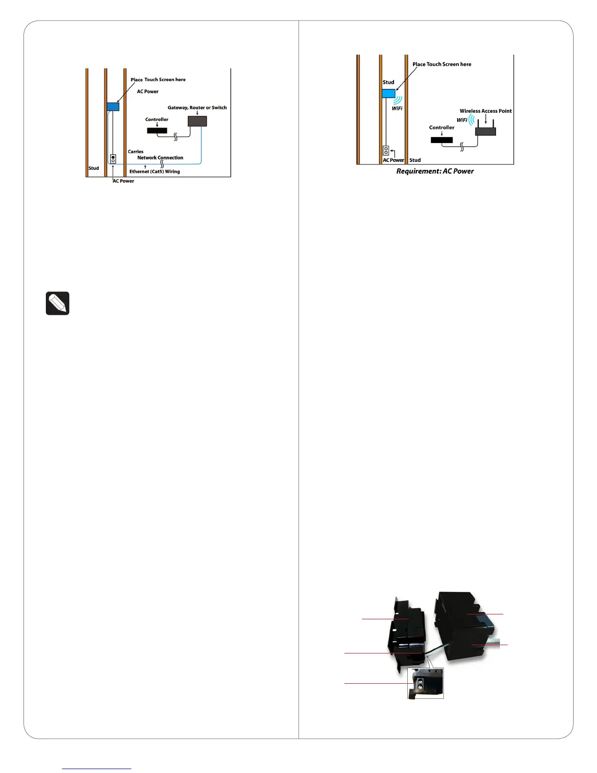
Figure 5. Ethernet - Requires a Connection to
Ethernet and AC Power
Option3:WiFiConnectionwithAC
Place the Touch Screen above a power source, for
example, an outlet. Ensure that you have WiFi in the
home (see Figure 6).
NOTES: (1) Video Intercom. Although this
device supports b/g/n, 802.11 b is not
supported for Video Intercom use. (2)
Wireless-N is recommended for Video
Intercom. See the Composer Pro User Guide
for details about the 7” In-Wall Touch Screen
with Camera properties.
WirelessNetworkLimitations
Many WiFi Access Points handle Multicasts
(WiFi simultaneously sent to multiple devices,
for example, when the 7” In-Wall Touch Screen
with Camera broadcasts video to all stations)
by slowing down transmission speed to the
1 Mb basic rate. This can cause overall WiFi
congestion in the WiFi network during the
broadcast. Video Intercom response times and
images may degrade at each device.
If a home requires a large number of WiFi
Video Intercom devices, ensure that you have
a robust WiFi network (possibly consisting of
multiple access points).
Figure 6. WiFi - Requires AC Power and WAP
Power Installation
Prepare the plastic power box for installation into the
back box by inserting either the Ethernet cable or the
AC power cable into the power box (see Figures 7
and 8), and then follow the instructions next.
ACPowerConnection
The steps below represent a typical U.S. installation.
1 Connect the wires to the AC power source for
the Touch Screen according to the national and
local electrical codes. Installation may require
alternative wires and the use of a terminal block.
2 Thread the power cable through the bottom back
hole of the back box to the terminal block (see
Figure 7).
3 Strip the black and white power wire ends to 1/4”
as necessary. Using a flathead screwdriver, loosen
the screws on the power box’s terminal block and
connect the power wires to each terminal (see
Figure 7).
4 Cap the ground wire from the wall if you are
using a plastic back box. Attach the ground wire
to the back box if using a metal back box.
Figure 7. AC Power Connection
5
Power Box
Back Box
Power Cable
Terminal
Block
Connect
Wires
to Terminal
Block